Cisco WS-X4515 Hardware Maintenance Manual - Page 30
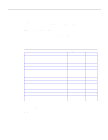
Unit Numbering Addresses for Dual Serial and Two Ethernet Modules
 |
UPC - 746320659190
View all Cisco WS-X4515 manuals
Add to My Manuals
Save this manual to your list of manuals |
Page 30 highlights
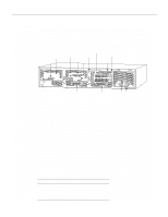
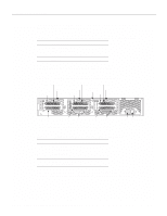
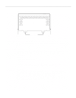
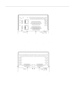
Preparing to Make Connections If the Token Ring module in Figure 2-2 was replaced by a second Ethernet module, the unit addresses would be as listed in Table 2-2. Table 2-2 Slot No. 1 2 3 Unit Numbering Addresses for Dual Serial and Two Ethernet Modules Interface Type Serial Port (Top) Serial Port (Bottom) Ethernet Ethernet Unit Address No. 1 0 0 1 Figure 2-3 shows a chassis configured with three dual serial modules. Figure 2-3 Router-Rear View Showing Serial Port Unit Numbering Dual serial module Slot 3 Serial 5 Dual serial module Dual serial module Slot 2 Serial 3 Chassis release screw Serial 1 Slot 1 AUX CONSOLE Serial 4 Serial 2 Auxiliary port Serial 0 Console port The unit numbering of these modules would be as listed in Table 2-3. INPUT 100-240VAC 50/60HZ 3.0-1.5 AMPS Power On/off switch Table 2-3 Slot No. 1 2 3 Unit Numbering Addresses for Three Dual Serial Modules Interface Type Serial Port (Top) Serial Port (Bottom) Serial Port (Top) Serial Port (Bottom) Serial Port (Top) Serial Port (Bottom) Unit Address No. 1 0 3 2 5 4 If the router is configured with fewer than three network processor modules, you must place a slot filler panel in the open slot to ensure proper airflow. Figure 2-4 shows a slot filler panel. H1402 a 2-8 Cisco 4000 Series Hardware Installation and Maintenance
-
 1
1 -
2
-
3
-
4
-
5
-
6
-
7
-
8
-
9
-
10
-
11
-
12
-
13
-
14
-
15
-
16
-
17
-
18
-
19
-
20
-
21
-
22
-
23
-
24
-
 25
25 -
 26
26 -
 27
27 -
 28
28 -
 29
29 -
 30
30 -
 31
31 -
 32
32 -
 33
33 -
 34
34 -
 35
35 -
36
-
37
-
38
-
39
-
40
-
41
-
42
-
43
-
44
-
45
-
46
-
47
-
48
-
49
-
50
-
51
-
52
-
53
-
54
-
55
-
56
-
57
-
58
-
59
-
60
-
61
-
62
-
63
-
64
-
65
-
66
-
67
-
68
-
69
-
70
-
71
-
72
-
73
-
74
-
75
-
76
-
77
-
78
-
79
-
80
-
81
-
82
-
83
-
84
-
85
-
86
-
87
-
88
-
89
-
90
-
91
-
92
-
93
-
94
-
95
-
96
-
97
-
98
-
99
-
100
-
101
-
102
-
103
-
104
-
105
-
106
-
107
-
108
-
109
-
110
-
111
-
112
-
113
-
114
-
115
-
116
-
117
-
118
-
119
-
120
-
121
-
122
-
123
-
124
-
125
-
126
-
127
-
128
-
129
-
130
-
131
-
132
-
133
-
134
-
135
-
136
-
137
-
138
-
139
-
140
-
141
-
142
-
143
 |
 |
