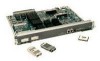
Cisco WS-X4515 Hardware Maintenance Manual - Page 87
Dual Serial Network Processor Module LED Indicators, Connect DSR, DTR, DCD, RTS, CTS
 |
UPC - 746320659190
View all Cisco WS-X4515 manuals
Add to My Manuals
Save this manual to your list of manuals |
Page 87 highlights
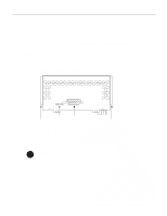
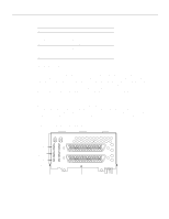
Reading Network Processor Module LED Indicators Table 4-1 Four Port Serial Network Processor Module LED Indicators LED Labels and Colors Indication LP (yellow) Loop CN (green) Connect (DSR, DTR, DCD, RTS, CTS) TD (green) Transmit data TC (green) Transmit clock RD (green) Receive data RC (green) Receive clock TC, RC, TD, and RD are on only when the associated line is changing state; if a line is stuck high or low, the LED is off. The names of the LEDs are given according to standard serial interface naming conventions. For example, TD (transmit data) is always associated with the data that is driven by the DTE regardless of whether the port on the four port serial module is a DTE or a DCE. This means that TD reflects output data when the port is a DTE and input data when the port is a DCE. RD (receive data) is controlled in a similar way. TC (transmit clock) and RC (receive clock) are always associated with the clocks that are driven by the DCE: outputs for a DCE port and inputs for a DTE. Dual Serial Network Processor Module LED Indicators The dual serial network processor module has two LED cards. As viewed from the front (see Figure 4-7), the left card is marked P-0 (for port 0), and the right card is marked P-1 (for port 1). The lower serial port is port 0, and the upper serial port is port 1, as shown on the labels. There are 10 LEDs per port. System network processor modules can be configured for either DTE or DCE. Figure 4-7 Serial Port Labeled V2 LEDs (4 green) LEDs (4 green) LEDs (1 yellow, 1 green) DO TXC DI RXC DCD RS TS1 TS2 LP DCE P-0 P-1 Alignment groove SERIAL (V2) 50-Pin serial ports PORT-1 PORT-0 Alignment groove H1484a Troubleshooting the Initial Hardware Configuration 4-7
-
 1
1 -
2
-
3
-
4
-
5
-
6
-
7
-
8
-
9
-
10
-
11
-
12
-
13
-
14
-
15
-
16
-
17
-
18
-
19
-
20
-
21
-
22
-
23
-
24
-
25
-
26
-
27
-
28
-
29
-
30
-
31
-
32
-
33
-
34
-
35
-
36
-
37
-
38
-
39
-
40
-
41
-
42
-
43
-
44
-
45
-
46
-
47
-
48
-
49
-
50
-
51
-
52
-
53
-
54
-
55
-
56
-
57
-
58
-
59
-
60
-
61
-
62
-
63
-
64
-
65
-
66
-
67
-
68
-
69
-
70
-
71
-
72
-
73
-
74
-
75
-
76
-
77
-
78
-
79
-
80
-
81
-
 82
82 -
 83
83 -
 84
84 -
 85
85 -
 86
86 -
 87
87 -
 88
88 -
 89
89 -
 90
90 -
 91
91 -
 92
92 -
93
-
94
-
95
-
96
-
97
-
98
-
99
-
100
-
101
-
102
-
103
-
104
-
105
-
106
-
107
-
108
-
109
-
110
-
111
-
112
-
113
-
114
-
115
-
116
-
117
-
118
-
119
-
120
-
121
-
122
-
123
-
124
-
125
-
126
-
127
-
128
-
129
-
130
-
131
-
132
-
133
-
134
-
135
-
136
-
137
-
138
-
139
-
140
-
141
-
142
-
143
 |
 |
