Compaq 6000 Maintenance & Service Guide: HP Compaq 6000 and 6080 Pro Busin - Page 124
CAUTION, Installing Guide Screws in the Optical Drive
 |
UPC - 894582579463
View all Compaq 6000 manuals
Add to My Manuals
Save this manual to your list of manuals |
Page 124 highlights
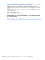
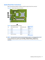
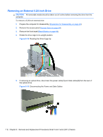
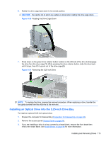
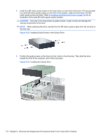
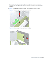
4. Install four M3 metric guide screws in the lower holes on each side of the drive. HP has provided four extra M3 metric guide screws on the front of the chassis, under the front bezel. The M3 metric guide screws are black. Refer to Installing and Removing Drives on page 109 for an illustration of the extra M3 metric guide screws location. CAUTION: Use only 5-mm long screws as guide screws. Longer screws can damage the internal components of the drive. NOTE: When replacing the drive, transfer the four M3 metric guide screws from the old drive to the new one. Figure 8-22 Installing Guide Screws in the Optical Drive 5. Position the guide screws on the drive into the J-slots in the drive bay. Then slide the drive toward the front of the computer until it locks into place. Figure 8-23 Installing the Optical Drive 114 Chapter 8 Removal and Replacement Procedures Small Form Factor (SFF) Chassis
-
 1
1 -
2
-
3
-
4
-
5
-
6
-
7
-
8
-
9
-
10
-
11
-
12
-
13
-
14
-
15
-
16
-
17
-
18
-
19
-
20
-
21
-
22
-
23
-
24
-
25
-
26
-
27
-
28
-
29
-
30
-
31
-
32
-
33
-
34
-
35
-
36
-
37
-
38
-
39
-
40
-
41
-
42
-
43
-
44
-
45
-
46
-
47
-
48
-
49
-
50
-
51
-
52
-
53
-
54
-
55
-
56
-
57
-
58
-
59
-
60
-
61
-
62
-
63
-
64
-
65
-
66
-
67
-
68
-
69
-
70
-
71
-
72
-
73
-
74
-
75
-
76
-
77
-
78
-
79
-
80
-
81
-
82
-
83
-
84
-
85
-
86
-
87
-
88
-
89
-
90
-
91
-
92
-
93
-
94
-
95
-
96
-
97
-
98
-
99
-
100
-
101
-
102
-
103
-
104
-
105
-
106
-
107
-
108
-
109
-
110
-
111
-
112
-
113
-
114
-
115
-
116
-
117
-
118
-
 119
119 -
 120
120 -
 121
121 -
 122
122 -
 123
123 -
 124
124 -
 125
125 -
 126
126 -
 127
127 -
 128
128 -
 129
129 -
130
-
131
-
132
-
133
-
134
-
135
-
136
-
137
-
138
-
139
-
140
-
141
-
142
-
143
-
144
-
145
-
146
-
147
-
148
-
149
-
150
-
151
-
152
-
153
-
154
-
155
-
156
-
157
-
158
-
159
-
160
-
161
-
162
-
163
-
164
-
165
-
166
-
167
-
168
-
169
-
170
-
171
-
172
-
173
-
174
-
175
-
176
-
177
-
178
-
179
-
180
-
181
-
182
-
183
-
184
-
185
-
186
-
187
-
188
-
189
-
190
-
191
-
192
-
193
-
194
-
195
-
196
-
197
-
198
-
199
-
200
-
201
-
202
-
203
-
204
-
205
-
206
-
207
-
208
-
209
-
210
-
211
-
212
-
213
-
214
-
215
-
216
-
217
-
218
-
219
-
220
-
221
-
222
-
223
-
224
-
225
 |
 |