Compaq 6000 Maintenance & Service Guide: HP Compaq 6000 and 6080 Pro Busin - Page 89
Power Switch/LED Assembly
 |
UPC - 894582579463
View all Compaq 6000 manuals
Add to My Manuals
Save this manual to your list of manuals |
Page 89 highlights
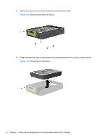
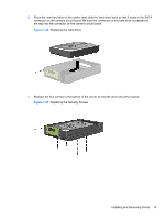
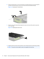
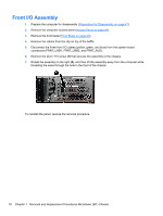
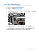
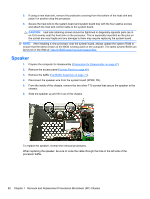
Power Switch/LED Assembly 1. Prepare the computer for disassembly (Preparation for Disassembly on page 47). 2. Remove the access panel (Access Panel on page 48). 3. Remove the front bezel (Front Bezel on page 49). 4. Disconnect the cable from the system board (P5, PB/LED). 5. With the computer on its side, press on the bottom of the assembly (1) and rotate upward (2) to disengage it from the chassis. 6. Pull the assembly away from the chassis while threading the cable through the hole in front of the chassis. To reinstall the assembly, insert the tabs on the right side of the assembly into the slots in the chassis, and then rotate the left side of the assembly down until it snaps into place. Power Switch/LED Assembly 79
-
 1
1 -
2
-
3
-
4
-
5
-
6
-
7
-
8
-
9
-
10
-
11
-
12
-
13
-
14
-
15
-
16
-
17
-
18
-
19
-
20
-
21
-
22
-
23
-
24
-
25
-
26
-
27
-
28
-
29
-
30
-
31
-
32
-
33
-
34
-
35
-
36
-
37
-
38
-
39
-
40
-
41
-
42
-
43
-
44
-
45
-
46
-
47
-
48
-
49
-
50
-
51
-
52
-
53
-
54
-
55
-
56
-
57
-
58
-
59
-
60
-
61
-
62
-
63
-
64
-
65
-
66
-
67
-
68
-
69
-
70
-
71
-
72
-
73
-
74
-
75
-
76
-
77
-
78
-
79
-
80
-
81
-
82
-
83
-
 84
84 -
 85
85 -
 86
86 -
 87
87 -
 88
88 -
 89
89 -
 90
90 -
 91
91 -
 92
92 -
 93
93 -
 94
94 -
95
-
96
-
97
-
98
-
99
-
100
-
101
-
102
-
103
-
104
-
105
-
106
-
107
-
108
-
109
-
110
-
111
-
112
-
113
-
114
-
115
-
116
-
117
-
118
-
119
-
120
-
121
-
122
-
123
-
124
-
125
-
126
-
127
-
128
-
129
-
130
-
131
-
132
-
133
-
134
-
135
-
136
-
137
-
138
-
139
-
140
-
141
-
142
-
143
-
144
-
145
-
146
-
147
-
148
-
149
-
150
-
151
-
152
-
153
-
154
-
155
-
156
-
157
-
158
-
159
-
160
-
161
-
162
-
163
-
164
-
165
-
166
-
167
-
168
-
169
-
170
-
171
-
172
-
173
-
174
-
175
-
176
-
177
-
178
-
179
-
180
-
181
-
182
-
183
-
184
-
185
-
186
-
187
-
188
-
189
-
190
-
191
-
192
-
193
-
194
-
195
-
196
-
197
-
198
-
199
-
200
-
201
-
202
-
203
-
204
-
205
-
206
-
207
-
208
-
209
-
210
-
211
-
212
-
213
-
214
-
215
-
216
-
217
-
218
-
219
-
220
-
221
-
222
-
223
-
224
-
225
 |
 |
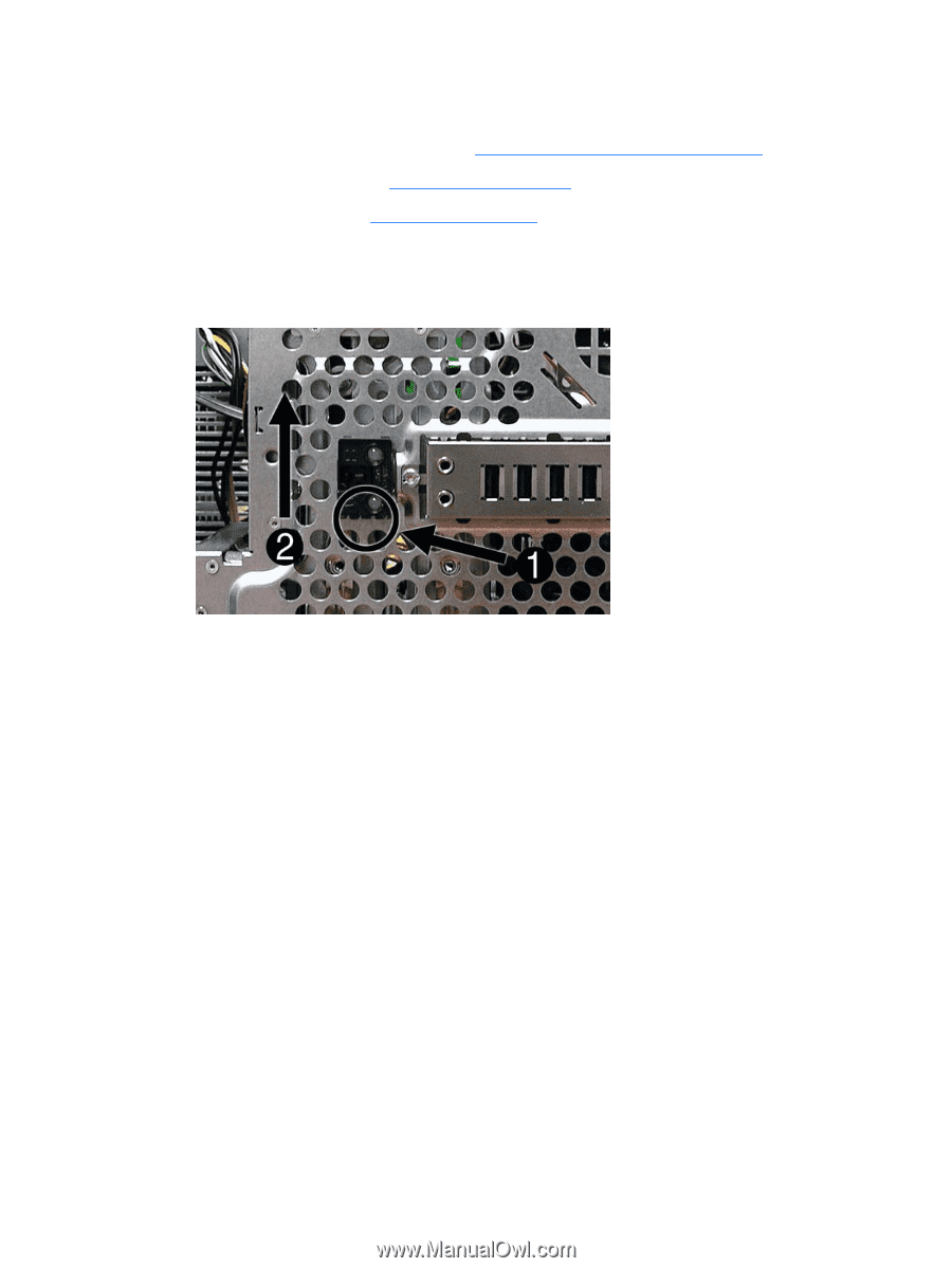
Power Switch/LED Assembly
1.
Prepare the computer for disassembly (
Preparation for Disassembly
on page
47
).
2.
Remove the access panel (
Access Panel
on page
48
).
3.
Remove the front bezel (
Front Bezel
on page
49
).
4.
Disconnect the cable from the system board (P5, PB/LED).
5.
With the computer on its side, press on the bottom of the assembly
(1)
and rotate upward
(2)
to
disengage it from the chassis.
6.
Pull the assembly away from the chassis while threading the cable through the hole in front of
the chassis.
To reinstall the assembly, insert the tabs on the right side of the assembly into the slots in the
chassis, and then rotate the left side of the assembly down until it snaps into place.
Power Switch/LED Assembly
79