Compaq 6000 Maintenance & Service Guide: HP Compaq 6000 and 6080 Pro Busin - Page 81
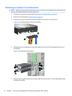
Installing an Internal 3.5-inch Hard Drive, Sliding a Hard Drive into the Drive Bay
 |
UPC - 894582579463
View all Compaq 6000 manuals
Add to My Manuals
Save this manual to your list of manuals |
Page 81 highlights
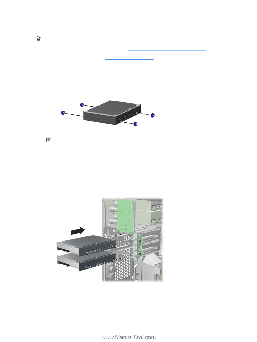
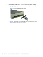
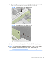
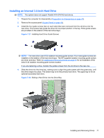
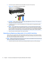
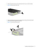
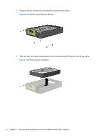
Installing an Internal 3.5-inch Hard Drive NOTE: The system does not support Parallel ATA (PATA) hard drives. 1. Prepare the computer for disassembly (Preparation for Disassembly on page 47). 2. Remove the access panel (Access Panel on page 48). 3. Install the four guide screws (two on each side) that were removed from the old drive into the new drive. The screws help guide the drive into its proper position in the bay. Extra guide screws are provided on the exterior of the hard drive bays. Figure 7-27 Installing Hard Drive Guide Screws NOTE: The hard drive uses 6-32 isolation mounting guide screws. Four extra guide screws are installed on the exterior of the hard drive bays. The HP-supplied isolation mounting guide screws are silver and blue. Refer to Installing and Removing Drives on page 61 for an illustration of the extra 6-32 isolation mounting guide screws location. If you are replacing a drive, transfer the guides screws from the old drive to the new one. 4. Slide the drive into the drive bay, making sure to align the guide screws with the guide slots, until the drive snaps into place. The bottom bay is for the primary hard drive. The upper bay is for an optional secondary hard drive. Figure 7-28 Sliding a Hard Drive into the Drive Bay Installing and Removing Drives 71
-
 1
1 -
2
-
3
-
4
-
5
-
6
-
7
-
8
-
9
-
10
-
11
-
12
-
13
-
14
-
15
-
16
-
17
-
18
-
19
-
20
-
21
-
22
-
23
-
24
-
25
-
26
-
27
-
28
-
29
-
30
-
31
-
32
-
33
-
34
-
35
-
36
-
37
-
38
-
39
-
40
-
41
-
42
-
43
-
44
-
45
-
46
-
47
-
48
-
49
-
50
-
51
-
52
-
53
-
54
-
55
-
56
-
57
-
58
-
59
-
60
-
61
-
62
-
63
-
64
-
65
-
66
-
67
-
68
-
69
-
70
-
71
-
72
-
73
-
74
-
75
-
 76
76 -
 77
77 -
 78
78 -
 79
79 -
 80
80 -
 81
81 -
 82
82 -
 83
83 -
 84
84 -
 85
85 -
 86
86 -
87
-
88
-
89
-
90
-
91
-
92
-
93
-
94
-
95
-
96
-
97
-
98
-
99
-
100
-
101
-
102
-
103
-
104
-
105
-
106
-
107
-
108
-
109
-
110
-
111
-
112
-
113
-
114
-
115
-
116
-
117
-
118
-
119
-
120
-
121
-
122
-
123
-
124
-
125
-
126
-
127
-
128
-
129
-
130
-
131
-
132
-
133
-
134
-
135
-
136
-
137
-
138
-
139
-
140
-
141
-
142
-
143
-
144
-
145
-
146
-
147
-
148
-
149
-
150
-
151
-
152
-
153
-
154
-
155
-
156
-
157
-
158
-
159
-
160
-
161
-
162
-
163
-
164
-
165
-
166
-
167
-
168
-
169
-
170
-
171
-
172
-
173
-
174
-
175
-
176
-
177
-
178
-
179
-
180
-
181
-
182
-
183
-
184
-
185
-
186
-
187
-
188
-
189
-
190
-
191
-
192
-
193
-
194
-
195
-
196
-
197
-
198
-
199
-
200
-
201
-
202
-
203
-
204
-
205
-
206
-
207
-
208
-
209
-
210
-
211
-
212
-
213
-
214
-
215
-
216
-
217
-
218
-
219
-
220
-
221
-
222
-
223
-
224
-
225
 |
 |