Compaq dc5850 Service Reference Guide: HP Compaq dc5850 Business PC - Page 107
Front USB Panel
 |
View all Compaq dc5850 manuals
Add to My Manuals
Save this manual to your list of manuals |
Page 107 highlights
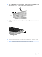
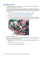
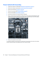
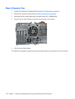
Front USB Panel 1. Prepare the computer for disassembly (Preparation for Disassembly on page 61). 2. Remove the computer access panel (Computer Access Panel on page 66). 3. Remove the front bezel (Front Bezel on page 67). 4. Disconnect the front I/O cable from the blue system board connector (P6) and the USB cable from the yellow system board connector (FRONT_USB, P24). 5. Stand the unit upright. 6. Remove the silver T15 screw that secures the panel to the chassis. 7. Pull the panel away from the unit while threading the wires between the drive cage and the baffle and through the hole in the front of the chassis. To reinstall the panel, reverse the removal procedure. Front USB Panel 95
-
 1
1 -
2
-
3
-
4
-
5
-
6
-
7
-
8
-
9
-
10
-
11
-
12
-
13
-
14
-
15
-
16
-
17
-
18
-
19
-
20
-
21
-
22
-
23
-
24
-
25
-
26
-
27
-
28
-
29
-
30
-
31
-
32
-
33
-
34
-
35
-
36
-
37
-
38
-
39
-
40
-
41
-
42
-
43
-
44
-
45
-
46
-
47
-
48
-
49
-
50
-
51
-
52
-
53
-
54
-
55
-
56
-
57
-
58
-
59
-
60
-
61
-
62
-
63
-
64
-
65
-
66
-
67
-
68
-
69
-
70
-
71
-
72
-
73
-
74
-
75
-
76
-
77
-
78
-
79
-
80
-
81
-
82
-
83
-
84
-
85
-
86
-
87
-
88
-
89
-
90
-
91
-
92
-
93
-
94
-
95
-
96
-
97
-
98
-
99
-
100
-
101
-
 102
102 -
 103
103 -
 104
104 -
 105
105 -
 106
106 -
 107
107 -
 108
108 -
 109
109 -
 110
110 -
 111
111 -
 112
112 -
113
-
114
-
115
-
116
-
117
-
118
-
119
-
120
-
121
-
122
-
123
-
124
-
125
-
126
-
127
-
128
-
129
-
130
-
131
-
132
-
133
-
134
-
135
-
136
-
137
-
138
-
139
-
140
-
141
-
142
-
143
-
144
-
145
-
146
-
147
-
148
-
149
-
150
-
151
-
152
-
153
-
154
-
155
-
156
-
157
-
158
-
159
-
160
-
161
-
162
-
163
-
164
-
165
-
166
-
167
-
168
-
169
-
170
-
171
-
172
-
173
-
174
-
175
-
176
-
177
-
178
-
179
-
180
-
181
-
182
-
183
-
184
-
185
-
186
-
187
-
188
-
189
-
190
-
191
-
192
-
193
-
194
-
195
-
196
-
197
-
198
-
199
-
200
-
201
-
202
-
203
-
204
-
205
-
206
-
207
-
208
-
209
-
210
-
211
-
212
-
213
-
214
-
215
-
216
-
217
-
218
-
219
-
220
-
221
-
222
-
223
-
224
-
225
-
226
-
227
-
228
-
229
-
230
-
231
-
232
-
233
-
234
-
235
-
236
-
237
-
238
-
239
-
240
-
241
-
242
-
243
-
244
-
245
-
246
-
247
-
248
-
249
 |
 |

Front USB Panel
1.
Prepare the computer for disassembly (
Preparation for Disassembly
on page
61
).
2.
Remove the computer access panel (
Computer Access Panel
on page
66
).
3.
Remove the front bezel (
Front Bezel
on page
67
).
4.
Disconnect the front I/O cable from the blue system board connector (P6) and the USB cable from
the yellow system board connector (FRONT_USB, P24).
5.
Stand the unit upright.
6.
Remove the silver T15 screw that secures the panel to the chassis.
7.
Pull the panel away from the unit while threading the wires between the drive cage and the baffle
and through the hole in the front of the chassis.
To reinstall the panel, reverse the removal procedure.
Front USB Panel
95