Craftsman 21419 Operation Manual - Page 6
Blade, Tracking, Guides, Upper
 |
View all Craftsman 21419 manuals
Add to My Manuals
Save this manual to your list of manuals |
Page 6 highlights
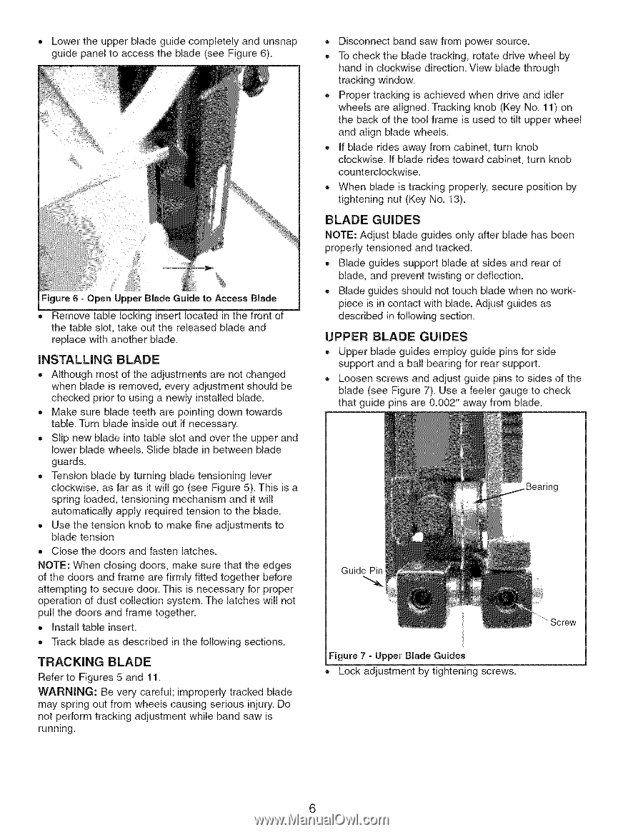
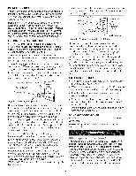
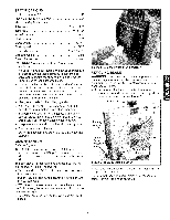
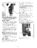
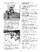
• Lower the upper blade guide completely and unsnap guide panel to access the blade (see Figure 6). Figure 6 = Open upper Blade Guide to Access Blade • Remove table locking insert located in the front of the table slot, take out the released blade and replace with another blade. INSTALLING BLADE • Although most of the adjustments are not changed when blade is removed, every adjustment should be checked prior to using a newly installed blade. • Make sure blade teeth are pointing down towards table. Turn blade inside out if necessary. • Slip new blade into table slot and over the upper and lower blade wheels. Slide blade in between blade guards. • Tension blade by turning blade tensioning lever clockwise, as far as it will go (see Figure 5). This is a spring loaded, tensioning mechanism and it will automatically apply required tension to the blade. • Use the tension knob to make fine adjustments to blade tension Close the doors and fasten latches. NOTE: When closing doors, make sure that the edges of the doors and frame are firmly fitted together before attempting to secure door. This is necessary for proper operation of dust collection system. The latches will not pull the doors and frame together. • Install table insert. Track blade as described in the following sections. TRACKING BLADE Refer to Figures 5 and 11. WARNING: Be very careful; improperly tracked blade may spring out from wheels causing serious injury. Do not perform tracking adjustment while band saw is running. • Disconnect band saw from power source. • To check the blade tracking, rotate drive wheel by hand in clockwise direction. View blade through tracking window. Proper tracking is achieved when drive and idler wheels are aligned. Tracking knob (Key No. 11) on the back of the tool frame is used to tilt upper wheel and align blade wheels. If blade rides away from cabinet, turn knob clockwise. If blade rides toward cabinet, turn knob counterclockwise. When blade is tracking properly, secure position by tightening nut (Key No. 13). BLADE GUIDES NOTE: Adjust blade guides only after blade has been properly tensioned and tracked. • Blade guides support blade at sides and rear of blade, and prevent twisting or deflection. Blade guides should not touch blade when no workpiece is in contact with blade. Adjust guides as described in following section. UPPER BLADE GUIDES = Upper blade guides employ guide pins for side support and a ball bearing for rear support. Loosen screws and adjust guide pins to sides of the blade (see Figure 7). Use a feeler gauge to check that guide pins are 0.002" away from blade. Guide Pin Bearing Figure 7 = Upper Blade Guides Lock adjustment by tightening screws. 6
-
 1
1 -
 2
2 -
 3
3 -
 4
4 -
 5
5 -
 6
6 -
 7
7 -
 8
8 -
 9
9 -
 10
10 -
 11
11 -
 12
12 -
13
-
14
-
15
-
16
-
17
-
18
-
19
-
20
-
21
-
22
-
23
-
24
 |
 |