Craftsman 29906 Owners Manual - Page 16
To Remove, Guard
 |
View all Craftsman 29906 manuals
Add to My Manuals
Save this manual to your list of manuals |
Page 16 highlights
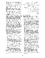
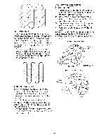
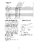
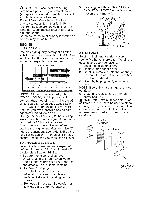
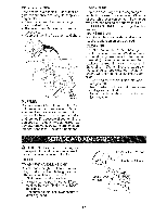
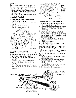
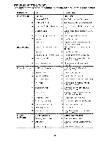
TIRE CARE _ILCAUTION: When mounting tires, un- less beads are seated, ovednflation can cause an explosion. • Maintain 20 pounds of tire pressure. If tire pressures are not equal, tiller will pull to one side. • Keep tires free of gasoline can damage rubber. TO REMOVE WHEEL or oil which . Place blocks under transmission to keep tiller from tipping. 2. Remove hairpin clip and clevis pin from wheel. 3. Remove wheel and tire. 4. Repair tire and reassemble. Clevis Pin tire 3 Hairpin Clip TO REMOVE BELT GUARD NOTE: For ease of removal, remove hairpin clip and clevis pin from left wheel. Pull wheel out from tiller about 1 inch. 1. Remove two (2) screws from side of belt guard. 2. Remove hex nut and washer from bottom of belt guard (located behind wheel). 3. Pull belt guard out and away from unit. 4. Replace belt guard by reversing above procedure. / \ Screws Belt Guard Hex and Washer (Located Behind Tire) Hairpin Clip and Clevis Pin TO REPLACE GROUND DRIVE BELT 1. Remove belt guard as described in "TO REMOVE BELT GUARD". 2. Remove old belt by slipping off engine pulley first then remove from transmission pulley. 3. Place new belt in groove of transmis- sion pulley and into engine pulley. BELT MUST BE IN GROOVE ON TOP OF IDLER PULLEY, NOTE POSITION OF BELT TO GUIDES. 4. Check belt adjustment as described below. 5. Replace belt guard. 6. Reposition wheel and replace pin and hairpin clip. clevis GROUND DRIVE BELT ADJUSTMENT For proper belt tension, the extension spring should have about 5/8 inch stretch when drive control bar is in "ENGAGED" position. This tension can be attained as follows: 1. Loosen cable clip screw securing the drive control cable. 2. Slide cable forward for less tension and rearward for more tension until about 5/8 inch stretch is obtained while the drive control bar is engaged. 3. Tighten cable clip screw securely. Engine Pulley\ Clip Screw Drive Control Cable Idler Pulley Transmission Pulley Extension Spring 16 More Tension
-
 1
1 -
2
-
3
-
4
-
5
-
6
-
7
-
8
-
9
-
10
-
 11
11 -
 12
12 -
 13
13 -
 14
14 -
 15
15 -
 16
16 -
 17
17 -
 18
18 -
 19
19 -
 20
20 -
 21
21 -
22
-
23
-
24
-
25
-
26
-
27
-
28
-
29
-
30
-
31
-
32
-
33
-
34
-
35
-
36
-
37
-
38
-
39
-
40
-
41
-
42
-
43
-
44
-
45
-
46
-
47
-
48
-
49
-
50
-
51
-
52
-
53
-
54
-
55
-
56
-
57
-
58
-
59
-
60
-
61
-
62
-
63
-
64
-
65
-
66
-
67
-
68
-
69
-
70
-
71
-
72
-
73
-
74
-
75
-
76
-
77
-
78
-
79
-
80
-
81
-
82
-
83
-
84
-
85
-
86
-
87
-
88
-
89
-
90
-
91
-
92
-
93
-
94
-
95
-
96
-
97
-
98
-
99
-
100
-
101
-
102
-
103
-
104
 |
 |
