Craftsman 29906 Owners Manual - Page 59
Remove, Tiller, Crate, Check, Handle, Height
 |
View all Craftsman 29906 manuals
Add to My Manuals
Save this manual to your list of manuals |
Page 59 highlights
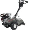
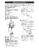
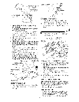
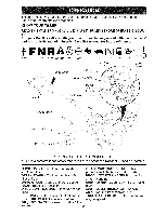
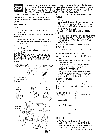
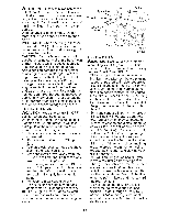
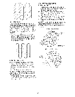
Handle Column Cables Loosen Handle Lock Lever to Move CONNECT Cable Clip handles 14 SHIFT ROD 1. Insert end of shift rod farthest from bend into hole of shift lever indicator. 4. Insert pivot bolt in front part of plate and tighten. 5. Cut down remaining corners of carton and lay panels flat. 6. Lower the handle assembly. Tighten nut on carriage bolt so handle moves with some resistance. This will allow for easier adjustment. 7. Place flat washer on threaded end of handle lock lever. 8. Insert handle lock lever through handle base and gearcase. Screw in handle lock lever just enough to hold lever in place. 9. Insert second handle lock (with teeth inward) in the slot of the handle base (just inside of washer). 10. Raise handle assembly to highest position and securely tighten handle lock lever by rotating clockwise. Leaving handle assembly in highest position will make it easier to connect shift rod. 2. Insert hairpin dip through hole of shift rod to secure with bend of clip on right side. Attach this End To shift _ Lever Indicator Shift Rod Hairpin Clip \ Shift Rod Shift Lever Indicator Flat Washer Handle Lock REMOVE TILLER FROM CRATE Handle Lock Gearcase Slot Lever \ 1. Adjust handle assemby to lowest posi- tion. Be sure lock lever is tightened securely. 2. Make sure shift lever indicator is in "N" Rear Cartridge Bolt / Handle Base Pivot Bolt _oc nut INSERT CABLE CLIP • Insert plastic came clip into hole on the back of handle column. Push cables into clip. (neutral) position. 3. Tilt tiller forward by lifting handle. Separate cardboard cover from leveling shield. 4. Rotate tiller handle to the right and pull tiller out of carton. CHECK TiRE PRESSURE The tires on your unit were overinflated at the factory for shipping purposes, Correct and equal tire pressure is important for best tilling performance. • Reduce tire pressure to 20 PSi. HANDLE HEIGHT • Handle height may be adjusted to better suit operator. (See "TO ADJUST HANDLE HEIGHT" in the Service and Adjustments section of this manual). 7
-
 1
1 -
2
-
3
-
4
-
5
-
6
-
7
-
8
-
9
-
10
-
11
-
12
-
13
-
14
-
15
-
16
-
17
-
18
-
19
-
20
-
21
-
22
-
23
-
24
-
25
-
26
-
27
-
28
-
29
-
30
-
31
-
32
-
33
-
34
-
35
-
36
-
37
-
38
-
39
-
40
-
41
-
42
-
43
-
44
-
45
-
46
-
47
-
48
-
49
-
50
-
51
-
52
-
53
-
 54
54 -
 55
55 -
 56
56 -
 57
57 -
 58
58 -
 59
59 -
 60
60 -
 61
61 -
 62
62 -
 63
63 -
 64
64 -
65
-
66
-
67
-
68
-
69
-
70
-
71
-
72
-
73
-
74
-
75
-
76
-
77
-
78
-
79
-
80
-
81
-
82
-
83
-
84
-
85
-
86
-
87
-
88
-
89
-
90
-
91
-
92
-
93
-
94
-
95
-
96
-
97
-
98
-
99
-
100
-
101
-
102
-
103
-
104
 |
 |
