Craftsman 88846 Operation Manual - Page 20
removed.See
 |
View all Craftsman 88846 manuals
Add to My Manuals
Save this manual to your list of manuals |
Page 20 highlights
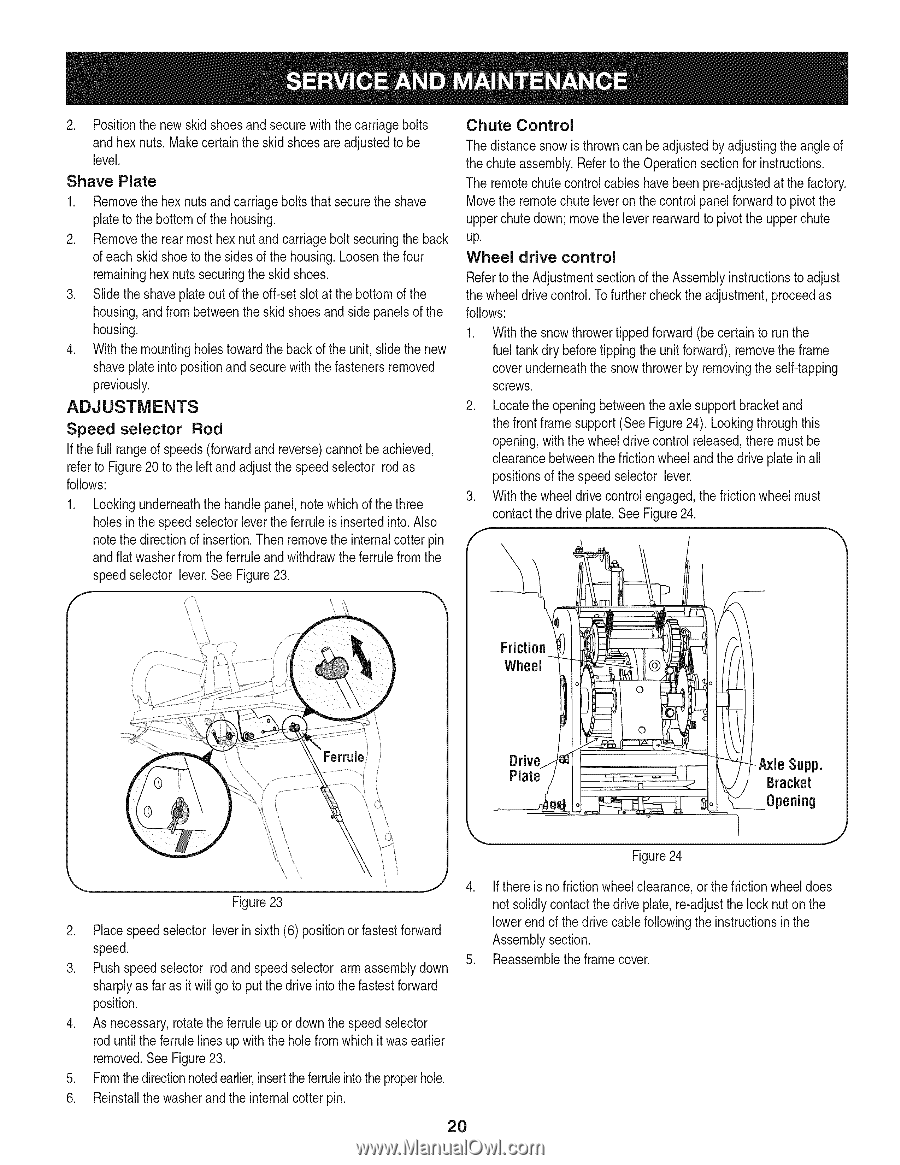
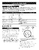
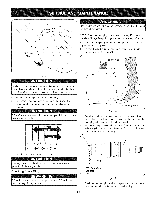
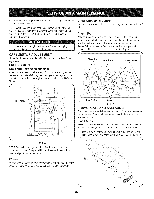
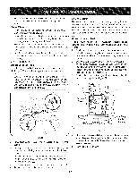
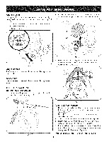
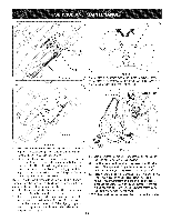
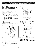
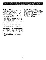
2. Positionthe new skid shoesand securewith the carriagebolts and hex nuts.Makecertainthe skid shoesare adjustedto be level. Shave Plate 1. Removethehex nuts and carriagebolts that securethe shave plateto the bottomof the housing. 2. Removethe rearmost hexnutand carriagebolt securingthe back of eachskid shoeto the sides of the housing.Loosenthefour remaininghexnuts securingthe skid shoes. 3. Slide theshaveplateout of the off-set slotat thebottomof the housing,and from betweenthe skid shoesand side panelsof the housing. 4. With the mountingholestowardthe back of the unit, slidethe new shaveplateinto positionand securewith the fastenersremoved previously. ADJUSTMENTS Speed selector Rod If thefull rangeof speeds(forwardand reverse)cannotbe achieved, referto Figure20 to the left and adjustthe speedselector rod as follows: 1. Lookingunderneaththe handlepanel,notewhich of thethree holesin the speedselectorleverthe ferruleis insertedinto. Also notethe directionof insertion.Thenremovethe internalcotter pin and flat washerfromthe ferruleand withdrawthe ferrulefrom the speedselector lever.See Figure23. Chute Control The distancesnow is throwncanbe adjustedbyadjustingthe angle of the chute assembly.Referto the Operationsectionfor instructions. The remotechutecontrolcables havebeen pre-adjustedat the factory. Movethe remotechute leveron the controlpanelforwardto pivot the upperchutedown; movethe leverrearwardto pivotthe upperchute up. Wheel drive control Referto theAdjustmentsectionof theAssemblyinstructiontos adjust the wheeldrivecontrol.Tofurther checkthe adjustment,proceedas follows: 1. With the snowthrowertippedforward(be certain to run the fuel tank dry beforetippingthe unitforward),removethe frame cover underneaththe snowthrowerby removingthe self-tapping screws. 2. Locatethe openingbetweenthe axle supportbracketand the front framesupport(See Figure24). Lookingthroughthis opening,with the wheeldrivecontrol released,there mustbe clearancebetweenthe frictionwheelandthe drive plateinall positionsof the speedselector lever. 3. With the wheeldrivecontrolengaged,the frictionwheel must contactthe driveplate. See Figure24. \\ \ Friction Wheel Ferrule \\ Figure24 4. If thereis no frictionwheelclearance,or thefrictionwheeldoes Figure23 notsolidlycontactthe drive plate,re-adjustthe lock nut on the 2. Placespeedselector leverin sixth(6) positionor fastestforward lowerend of the drivecablefollowingthe instructioninsthe speed. Assemblysection. 5. Reassembletheframe cover. 3. Pushspeedselector rodand speedselector armassemblydown sharplyas faras itwill go to putthe driveintothe fastestforward position. 4. As necessary,rotatethe ferruleup or downthe speedselector rod untilthe ferrulelinesup with the holefrom which itwas earlier removed.See Figure23. 5. Fromthedirectionnotedearlier,inserttheferruleintothe properhole. 6. Reinstallthe washerand the internalcotter pin. 2O
-
 1
1 -
2
-
3
-
4
-
5
-
6
-
7
-
8
-
9
-
10
-
11
-
12
-
13
-
14
-
 15
15 -
 16
16 -
 17
17 -
 18
18 -
 19
19 -
 20
20 -
 21
21 -
 22
22 -
 23
23 -
 24
24 -
 25
25 -
26
-
27
-
28
-
29
-
30
-
31
-
32
-
33
-
34
-
35
-
36
-
37
-
38
-
39
-
40
-
41
-
42
-
43
-
44
-
45
-
46
-
47
-
48
-
49
-
50
-
51
-
52
-
53
-
54
-
55
-
56
-
57
-
58
-
59
-
60
-
61
-
62
-
63
-
64
-
65
-
66
-
67
-
68
-
69
-
70
-
71
-
72
-
73
-
74
-
75
-
76
 |
 |