Craftsman 88846 Operation Manual - Page 21
Replacement
 |
View all Craftsman 88846 manuals
Add to My Manuals
Save this manual to your list of manuals |
Page 21 highlights
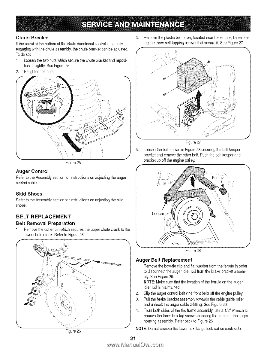
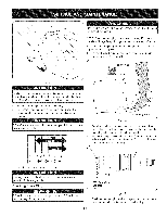
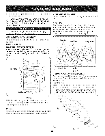
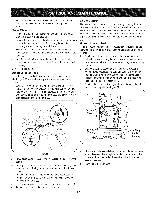
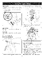
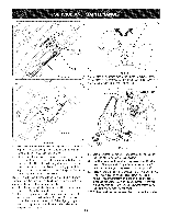
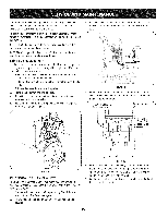
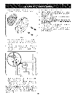
Chute Bracket If the spiralat the bottomof the chutedirectionalcontrol is not fully engagingwith the chuteassembly,the chute bracketcan be adjusted. Todo so: 1. Loosenthe two nuts which securethe chute bracketand reposition it slightly.See Figure25. 2. Retightenthenuts. 2. Removethe plasticbeltcover,locatednearthe engine,by removing thethree self-tappingscrewsthat secure it. See Figure27. \ / Figure25 Auger Control Referto the Assemblysectionfor instructionson adjustingtheauger controlcable. Figure27 3. Loosenthe boltshownin Figure28 securingthe beltkeeper bracketand removethe otherbolt. Pushthe belt keeperand bracketup off theengine pulley. Skid Shoes Referto the Assemblysectionfor instructionosn adjustingthe skid shoes. BELT REPLACEMENT Belt Removal Preparation 1. Removethe cotter pin whichsecuresthe upperchute crank tothe lowerchutecrank.Referto Figure26. Figure26 Figure28 Auger Belt Replacement 1. Removethe bow-tieclipand flat washerfromthe ferruleinorder to disconnecttheauger idlerrod fromthe brakebracketassembly. See Figure29. NOTE: Makesurethat the locationof the ferruleon the auger idlerrod is maintained. 2. Slip the augercontrol belt(the front belt)off the enginepulley. 3. Pullthe brakebracketassemblytowardsthe cableguide roller and unhooktheauger cablez-fitting.See Figure30. 4. Frombothsides of thethe frame assembly,usea 1/2"wrenchto removethe threehextap screwssecuringthe frameto theauger housingassembly.Referback to Figure26. NOTE: Donot removethe lowerhexflangelock nut on each side. 21
-
 1
1 -
2
-
3
-
4
-
5
-
6
-
7
-
8
-
9
-
10
-
11
-
12
-
13
-
14
-
15
-
 16
16 -
 17
17 -
 18
18 -
 19
19 -
 20
20 -
 21
21 -
 22
22 -
 23
23 -
 24
24 -
 25
25 -
 26
26 -
27
-
28
-
29
-
30
-
31
-
32
-
33
-
34
-
35
-
36
-
37
-
38
-
39
-
40
-
41
-
42
-
43
-
44
-
45
-
46
-
47
-
48
-
49
-
50
-
51
-
52
-
53
-
54
-
55
-
56
-
57
-
58
-
59
-
60
-
61
-
62
-
63
-
64
-
65
-
66
-
67
-
68
-
69
-
70
-
71
-
72
-
73
-
74
-
75
-
76
 |
 |