Craftsman 88846 Operation Manual - Page 8
Removing, Crate
 |
View all Craftsman 88846 manuals
Add to My Manuals
Save this manual to your list of manuals |
Page 8 highlights
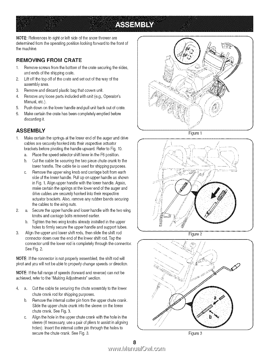
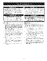
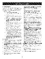
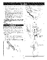
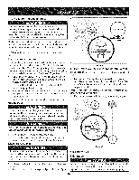
NOTE:Referencesto rightor left sideof the snowthrowerare determinedfrom the operatingpositionlookingforwardto the front of the machine. REMOVING FROM CRATE 1. Removescrewsfrom the bottomof thecrate securingthesides, and endsof the shippingcrate. 2. Lift off the topoff of the crate and set outof theway of the assemblyarea. 3. Removeand discard plasticbag thatcoversunit. 4. Removeany looseparts includedwith unit (e.g.,Operator's Manual,etc.). 5. Pushdownon the lowerhandleand pull unit backout of crate. 6. Makecertainthe crate has beencompletelyemptiedbefore discardingit. ASSEMBLY 1. Makecertainthe springsat the lowerend of the augerand drive cablesare securelyhookedintotheir respectiveactuator bracketsbeforepivotingthe handle upward.Referto Fig. 10. Y Figure 1 a. Placethe speedselectorshiftleverin the F6 position. b. Cut the cabletie securingthe two piecechute crank to the lowerhandle.Thecable tie is usedfor shippingpurposes. c. Removethe upperwingknoband carriageboltfrom each sideof the lowerhandle.Pull up on upper handleas shown in Fig. 1.Align upper handlewith the lowerhandle.Again, makecertainthe springsat the lowerend of the augerand drivecablesare securelyhookedintotheir respective actuatorbrackets.Also, removeany rubberbandssecuring thecables to the wingnuts. 2. a. Securethe upper handleand lowerhandlewith thetwo wing knobsand carriagebolts removedearlier. / b. Tightenthetwo wingknobsalreadyinstalledin the upper holesto firmlysecurethe upperhandleand supporttubes. J 3. Align the upperand lowershift rods, thenslidethe shift rod connectordownoverthe end of the lowershift rod.Tapthe connectoruntilthe lower rodis completelythroughtheconnector. See Fig.2. NOTE:If theconnectoris notproperlyassembled,the shift rodwill pivotand youwill notbe able to properlychangespeedsor direction. NOTE:If thefull rangeof speeds(forwardand reverse)can not be achieved,referto the "MakingAdjustments"section. . a. Cut the cabletie securingthe chute assemblyto the lower chutecrank rod for shippingpurposes. b. Removethe internalcotterpin from the upperchutecrank. Slide the upperchute crankinto the sleeveon the lower chutecrank.See Fig.3. c. Alignthe holein the upperchutecrank with the hole in the sleeve(If necessary,usea pairof pliersto assist in aligning holes). Insertthe internalcotter pin throughthe holesto securethe chutecrank.See Fig. 3. 8 Figure3
-
 1
1 -
2
-
 3
3 -
 4
4 -
 5
5 -
 6
6 -
 7
7 -
 8
8 -
 9
9 -
 10
10 -
 11
11 -
 12
12 -
 13
13 -
14
-
15
-
16
-
17
-
18
-
19
-
20
-
21
-
22
-
23
-
24
-
25
-
26
-
27
-
28
-
29
-
30
-
31
-
32
-
33
-
34
-
35
-
36
-
37
-
38
-
39
-
40
-
41
-
42
-
43
-
44
-
45
-
46
-
47
-
48
-
49
-
50
-
51
-
52
-
53
-
54
-
55
-
56
-
57
-
58
-
59
-
60
-
61
-
62
-
63
-
64
-
65
-
66
-
67
-
68
-
69
-
70
-
71
-
72
-
73
-
74
-
75
-
76
 |
 |