Cub Cadet CC 760ES CC 760ES Operator's Manual - Page 10
Unfolding the Handle, Attaching the Shift Lever - used
 |
View all Cub Cadet CC 760ES manuals
Add to My Manuals
Save this manual to your list of manuals |
Page 10 highlights
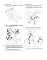
Unfolding the Handle 1. Remove the star knobs and carriage screws from the lower handle. See Fig.3-3. Attaching the Shift Lever 1. Remove the screw and the lock nut that secures the shift lever to the shift lever plate. See Fig. 3-5. 2. Remove the remaining screw and nut from the lower shift lever plate. See Fig. 3-5. Figure 3-3 2. Pivot the upper handle into operating position. Be careful not to crimp cables. See Fig. 3-4. Figure 3-5 3. Position the upper shift lever into a vertical position aligning the holes in the lever with the holes in the shift plate. See Fig. 3-6. Figure 3-4 3. Reinstall the carriage screws and knobs removed earlier. 4. Tighten the upper and lower star knobs and carriage screws to secure the upper handle to the lower handle. See Figure 3-6 Fig. 3-4. 4. Secure the lever to the plate using the two screws and two 5. The handle height can be adjusted to any of three nuts removed earlier. See Fig. 3-6 inset. positions. For instructions, refer to Handle Height in the Maintenance and Adjustments section of this manual. 10 Section 2 - Assembly & Set-Up
-
 1
1 -
2
-
3
-
4
-
 5
5 -
 6
6 -
 7
7 -
 8
8 -
 9
9 -
 10
10 -
 11
11 -
 12
12 -
 13
13 -
 14
14 -
 15
15 -
16
-
17
-
18
-
19
-
20
-
21
-
22
-
23
-
24
-
25
-
26
-
27
-
28
-
29
-
30
-
31
-
32
-
33
-
34
-
35
-
36
-
37
-
38
-
39
-
40
-
41
-
42
-
43
-
44
-
45
-
46
-
47
-
48
-
49
-
50
-
51
-
52
-
53
-
54
-
55
-
56
-
57
-
58
-
59
-
60
-
61
-
62
-
63
-
64
-
65
-
66
-
67
-
68
 |
 |
