Cub Cadet CC 760ES CC 760ES Operator's Manual - Page 9
Assembly & Set-Up - attachments
 |
View all Cub Cadet CC 760ES manuals
Add to My Manuals
Save this manual to your list of manuals |
Page 9 highlights
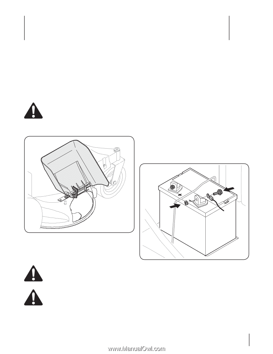
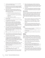
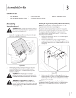
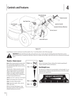
Assembly & Set-Up 3 Contents of Crate • One Lawn Mower • • One Lawn Mower Operator's Manual • One Oil Drain Tube One Engine Operator's Manual • One Deck Wash Hose Coupler Mower Set-Up Shipping Brace Removal Warning! Make sure the lawn mower's engine is off. Remove the ignition key (if so equipped) before removing the shipping brace. 1. Locate the shipping brace, if present, found on the right side of the cutting deck. See Fig. 3-1. Attaching the Negative Battery Cable (for Electric Start Models) NOTE: The positive battery terminal is marked Pos. (+). The negative battery terminal is marked Neg. (-). The positive cable (heavy red wire) is secured to the positive battery terminal (+) with a hex bolt and hex nut at the factory. The negative cable (heavy black wire) may be secured to the negative battery terminal at the factory. If it hasn't been attached, proceed as follows: 1. Remove the carriage bolt and hex nut from the negative cable (heavy black wire). 2. Remove the black plastic cover, if present, from the negative battery terminal and attach the negative cable to the negative battery terminal (-) with the bolt and hex nut. See Fig. 3-2. Figure 3-1 2. While holding the discharge chute with your left hand, remove the shipping brace with your right hand by grasping it between your thumb and index finger and rotating it clockwise. Warning! The shipping brace is used for Figure 3-2 packaging purposes only. Remove and discard the 3. Make certain the hold-down rod is in position over the shipping brace before operating your lawn mower. battery, securing it in place and make certain that the red rubber boot covers the positive battery terminal to help protect it from corrosion. Warning! The mowing deck is capable of throwing objects. Failure to operate the mower without the discharge cover in the proper operating position could result in serious personal injury and/ or property damage. NOTE: If the battery is put into service after the date shown on top/side of battery, charge the battery as instructed in the Maintenance section of this manual prior to operating the mower. 9
-
 1
1 -
2
-
3
-
 4
4 -
 5
5 -
 6
6 -
 7
7 -
 8
8 -
 9
9 -
 10
10 -
 11
11 -
 12
12 -
 13
13 -
 14
14 -
15
-
16
-
17
-
18
-
19
-
20
-
21
-
22
-
23
-
24
-
25
-
26
-
27
-
28
-
29
-
30
-
31
-
32
-
33
-
34
-
35
-
36
-
37
-
38
-
39
-
40
-
41
-
42
-
43
-
44
-
45
-
46
-
47
-
48
-
49
-
50
-
51
-
52
-
53
-
54
-
55
-
56
-
57
-
58
-
59
-
60
-
61
-
62
-
63
-
64
-
65
-
66
-
67
-
68
 |
 |