Cub Cadet ZTX4 54 Operation Manual - Page 11
Hour Meter & LCD Service Minder If equipped
 |
View all Cub Cadet ZTX4 54 manuals
Add to My Manuals
Save this manual to your list of manuals |
Page 11 highlights
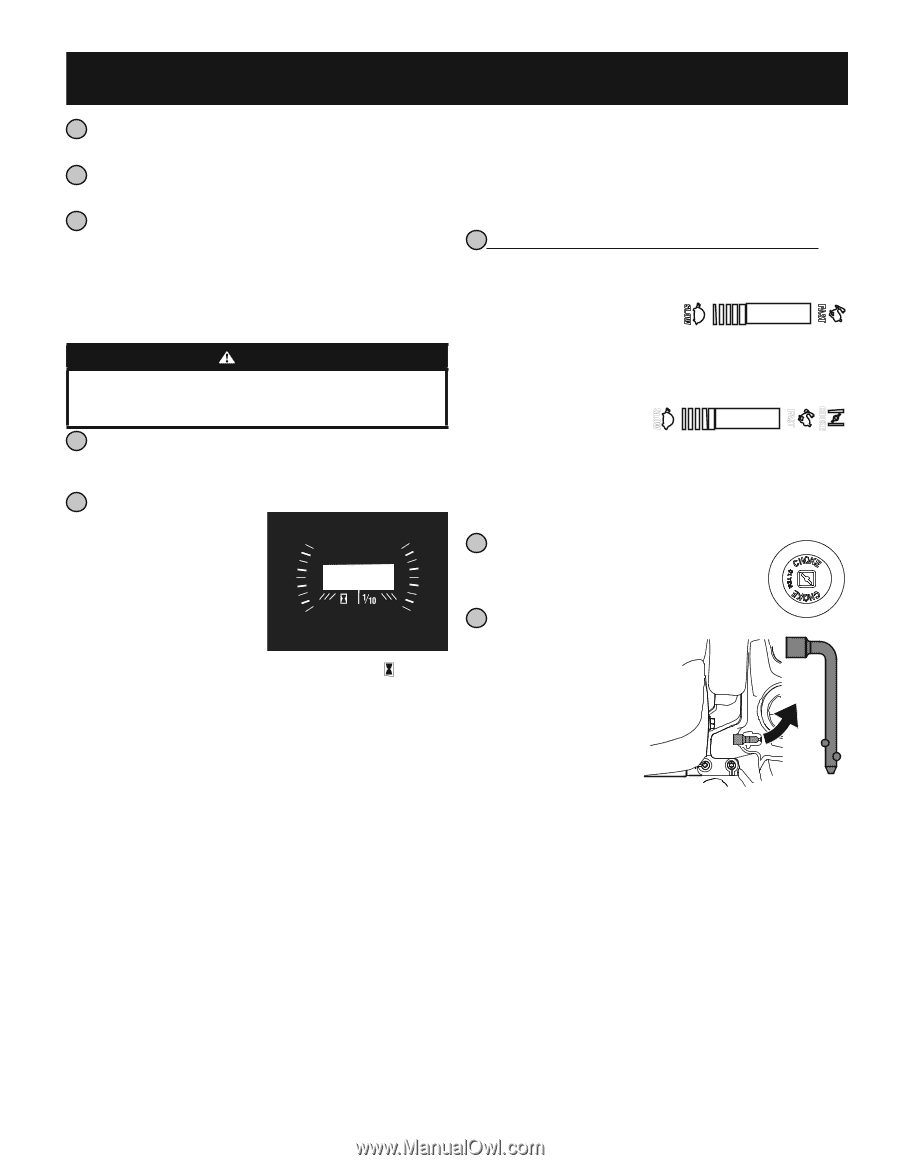
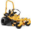
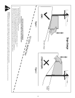
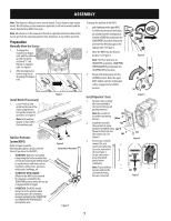
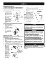
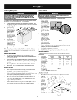
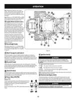
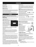
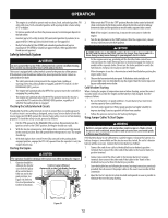
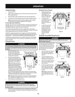
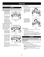
OPERATION 8 Cup Holder The cup holder is located on the top of the console. 9 Storage Tray The storage tray is located to the rear of the console. 10 Fuel Tank Cap Turn the fill cap counter clockwise and pull upward to remove. The fuel cap is tethered to the tractor to prevent its loss. Do not attempt to remove the cap from the tractor. Fill tank to ½" (12.7 mm)below the bottom of the filler neck, allowing some space in the tank for fuel expansion. Do not overfill the tank. Push the cap downward on the fuel tank fill neck and turn at least two clicks clockwise to tighten. Always re-install the fuel cap tightly onto the fuel tank after removing. WARNING Never fill the fuel tank when the engine is running. If the engine is hot from recently running, allow to cool for at least five minutes before refueling. Highly flammable gasoline could splash onto the engine and cause a fire. 11 Fuel Gauge The fuel gauge is located to the left of the seat and provides an indicator of the current fuel level in the tank. 12 Hour Meter & LCD Service Minder (If equipped) The LCD service minder will remind the operator of maintenance intervals for changing the engine oil, air filter service, low engine and low battery warnings. When the key is rotated out of the STOP position but is not in the START position, the LCD service minder & hour meter will briefly display the battery voltage, followed by the tractor's accumulated hours. Note: When the ignition key is out of the STOP position the hourglass symbol is illuminated/blinks to indicate it is recording the hours of tractor operation, regardless of whether the engine has been started. Change Oil The LCD screen will alternate the letters "CHG", followed by "OIL", followed by "SOON", followed by the meter's accumulated time. "CHG/OIL/SOON/TIME" will alternate on the display for 7 minutes after the meter reaches 50 hours. This oil service minder interval will occur every 50 hours. Before the interval expires, change the engine oil as instructed in the Engine Operator's Manual Low Oil Note: The low oil pressure function only works if the engine is equipped with an oil pressure switch. The LCD screen will alternate the letters "LO" followed by "OIL", followed by the meter's accumulated time, which indicates the engine has low oil pressure. This is common when starting an engine. The indicator will remain active until the engine sufficiently builds pressure after starting. If it remains on with the engine at full speed and after a few minutes of operation, stop the tractor immediately and check the engine oil level and add as instructed in the Engine Operator's Manual. If the oil level is correct and the indicator persists, contact an authorized service dealer. Low Battery At startup, the battery voltage will briefly display, then changes to accumulated hours. The letters "LO" followed by the letters "BATT" will display, followed by the meter's accumulated time. "LO/BATT/TIME" is displayed on the LCD when the voltage drops below 11.5 volts. When this occurs, the battery is in need of a charge or the engine's charging system is not generating sufficient amperage. Charge the battery as instructed in the Product Care section of this manual or have the charging system checked by your local service dealer. Air Filter Service The LCD screen will display the letters "CLN" followed by the letters "AIR", followed by "FILT", followed by the meter's accumulated time. "CLN/AIR/FILT/TIME" will alternate on the display for 7 minutes after the meter reaches 25 hours. This air filter service minder time interval will be every 25 hours. On intervals that are common with oil service, the oil message will be displayed first followed by the air filter message. 13 Throttle/Choke Control Lever or Throttle Control Lever Note: When set in a given position, a uniform engine speed will be maintained. Throttle Control Lever (If equipped) Push the throttle control lever forward to increase the engine speed. The tractor is designed to operate with the throttle control lever at full throttle (FAST) when the tractor is being driven and the tractor deck is engaged. Pull the throttle control lever rearward to decrease the engine speed. Throttle/Choke Control Lever (If equipped) Push the throttle/choke control lever forward to increase the engine speed. The tractor is designed to operate with the throttle/choke control lever at full throttle (FAST) when the tractor is being driven and the mower deck is engaged. Pull the throttle/choke control lever rearward to decrease the engine speed. When starting the engine, push the control lever fully forward into the "CHOKE" position.After starting and warming the engine, move the control handle rearward until you feel it move past the choke detent. Throttle is not meant to control unit speed, throttle should remain in high speed while operating blades. 14 Choke Control (If equipped) The choke control determines the position of the engine choke. Pull the knob out to choke the engine; push the knob in to open the choke. 15 Multi-Tool The multi-tool (a) is located on the back of the right console. The multi-tool (a) can be used as a deck lift lockout, adjust the height of the lapbar drive control levers, drive control lever stop adjustment and can be used as a removal tool with the ½" socket end. See the Service and Maintenance section for more information on multitool (a) usage. See Figure 17. Headlights (Not shown) Figure 17 The headlights are located on the front of the frame. The headlights are ON whenever the ignition key is rotated out of the STOP position and OFF when the ignition key is moved to the STOP position. Seat Adjustment Lever (Not shown) The seat adjustment lever is located under the seat. The seat adjustment lever allows for adjustment forward or backward of the operator's seat. Refer to the Assembly & Set-Up section for instructions on adjusting the seat position. Note: If your tractor is not equipped with a seat adjustment lever, it can be adjusted using the knobs on the underside of the seat. Refer to the Assembly section for instruction on adjusting the seat. Operation Before Operating Your Tractor • Before operation, refer to Maintenance Schedule chart located in this manual for regularly scheduled service items. 11
-
 1
1 -
2
-
3
-
4
-
5
-
 6
6 -
 7
7 -
 8
8 -
 9
9 -
 10
10 -
 11
11 -
 12
12 -
 13
13 -
 14
14 -
 15
15 -
 16
16 -
17
-
18
-
19
-
20
-
21
-
22
-
23
-
24
-
25
-
26
-
27
-
28
-
29
-
30
-
31
-
32
-
33
-
34
-
35
-
36
-
37
-
38
-
39
-
40
-
41
-
42
-
43
-
44
-
45
-
46
-
47
-
48
 |
 |