Cub Cadet ZTX4 54 Operation Manual - Page 21
Deck Removal
 |
View all Cub Cadet ZTX4 54 manuals
Add to My Manuals
Save this manual to your list of manuals |
Page 21 highlights
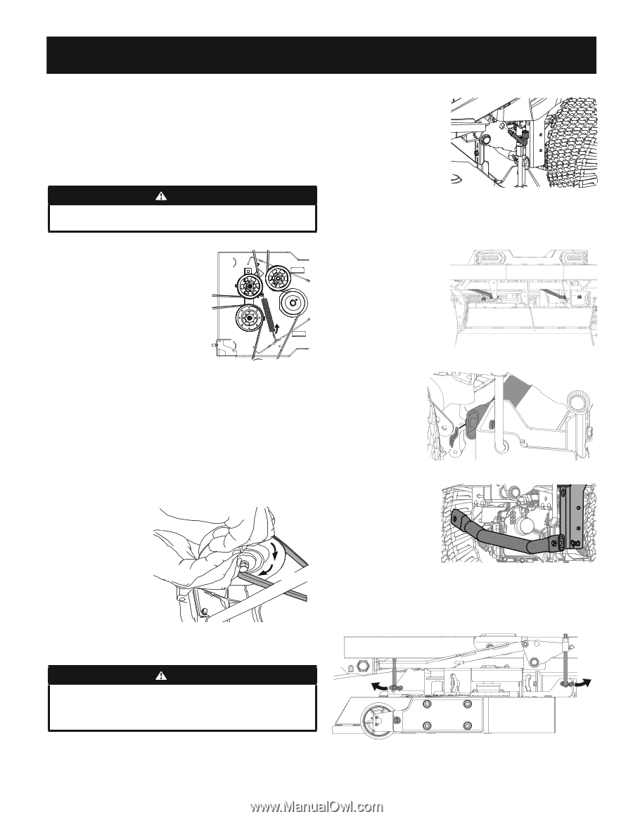
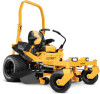
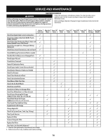
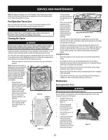
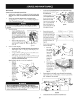
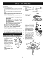
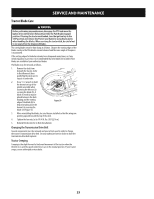
SERVICE AND MAINTENANCE Deck Removal 5. Remove the tractor deck from the tractor as follows: 1. Move the tractor to a level surface, disengage the PTO, stop the engine, place the RH and LH drive control levers fully outward into the park brake engaged position. 2. There are two methods for removing the belt, to remove the belt by releasing belt tension go on to step 3, to remove the belt by rolling the belt off the PTO pulley skip ahead to step 4. WARNING Use caution to avoid pinching your fingers when rolling the belt off the PTO pulley. 3. Release belt tension: a. Using the deck lift handle or the 6. deck lift pedal and knob, raise the deck to the position that provides the most horizontal run of the belt between the deck idler pulleys and the PTO pulley on the bottom of the engine. b. Remove the idler spring from the wireframe spring hook on the right sideof the center of the deck. See Figure 38. 7. 4. Roll the belt off the PTO pulley: Figure 38 a. Raise the deck to the position that provides the most horizontal run of the belt between the deck idler pulleys and the PTO pulley on the bottom of the engine. b. Sitting behind the tractor facing forward, reach beneath the tractor to grasp the belt at the front of the PTO pulley. c. Pull the left side of the belt rearward and downward while manually turning the PTO pulley to the right until the belt rides out onto the edge of the lower sheave of the pulley. Note: If pulling the right side of the belt, turn the pulley left. d. While still holding the PTO belt (a) downward, continue turning the PTO pulley (b) until the PTO belt (a) is rolled off the PTO pulley (b). Refer to Figure 39. (a) (b) 8. (a) e. Lower the deck into the lowest mowing position. Figure 39 WARNING The deck lift is spring-assisted and under tension. Injury can occur if spring-assisted deck lift is released suddenly. Always use the multi-tool to secure the deck lift in place. Do not attempt to use the deck lift pedal while the deck is locked with the multitool in this way. Use the deck lift pedal and deck lift knob to place the deck in the lowest position and use the multi-tool to lock the deck lift components in place. There are a pair of alignment holes by the rear wheel on the left side of the tractor (one on the frame and one on the deck lift arm) as shown in Figure 40. Ensure tool is fully inserted Figure 40 properly, locking the deck lift arm in place to the frame. Remove the two bow-tie pins from the deck rods that secure the front center lift link brackets on the frame to the front-center lift brackets on the deck and pull the front end of the rods out of place. See Figure 41. Remove the deck stabilizer bar at the rear of the deck: Figure 41 a. Remove the bow-tie cotter pin on the right side of the bar connecting the bar with the bracket on the deck. See Figure 42. Figure 42 b. Remove the bowtie cotter pin on the left side of the bar, connecting the bar with the bracket on the frame. See Figure 43. Figure 43 Remove the bow-tie pin from the bottom clevis end of each deck height adjust rod. There is one at the front and one at the rear on each side of the deck. See Figure 44. (Left side shown). Figure 44 9. Carefully manuever the deck out from beneath the tractor. 21
-
 1
1 -
2
-
3
-
4
-
5
-
6
-
7
-
8
-
9
-
10
-
11
-
12
-
13
-
14
-
15
-
 16
16 -
 17
17 -
 18
18 -
 19
19 -
 20
20 -
 21
21 -
 22
22 -
 23
23 -
 24
24 -
 25
25 -
 26
26 -
27
-
28
-
29
-
30
-
31
-
32
-
33
-
34
-
35
-
36
-
37
-
38
-
39
-
40
-
41
-
42
-
43
-
44
-
45
-
46
-
47
-
48
 |
 |