Cub Cadet ZTX4 54 Operation Manual - Page 20
Service
 |
View all Cub Cadet ZTX4 54 manuals
Add to My Manuals
Save this manual to your list of manuals |
Page 20 highlights
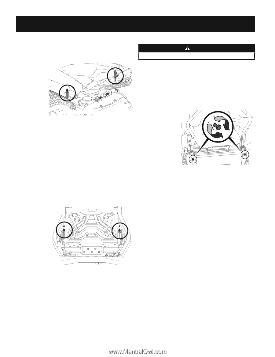
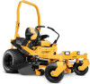
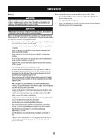
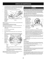
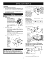
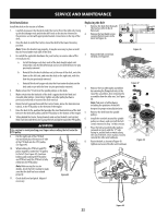
SERVICE AND MAINTENANCE 5. Locate the adjustment nuts on top of the deck lift rods on the left and right side of the tractor. There is one on each side at the front of the deck between the platform and lower frame tube, and one at each side of the rear of the deck near the front of the rear wheel. See Figure 35. 6. Remove the end cap from front deck lift rods and save for later reinstallation. 7. Rotate either the left side (front and rear) or right side (front and rear) nuts clockwise to raise the deck height or counterclockwise to lower the deck, depending on the needed adjustment. Lower Frame Not Shown for Clarity Figure 35 Note: Make adjustments in quarter-turn increments, and remeasure blade distance on both sides frequently. Leveling the Deck (Pitch/Front-to-Rear) The front of the deck should be between 2-6 mm) lower than the rear of the deck. Adjust if necessary as follows: 1. Park the tractor on a firm, level surface and place the deck lift knob in a middle position. 2. Ensure that all tires are properly inflated. 3. Ensure side-to-side level. 4. Rotate the blade nearest the discharge chute so that it is parallel with the tractor. 5. Measure the distance from the front of the blade tip to the ground and the rear of the blade tip to the ground. The first measurement taken should be between 2-6 mm) less than the second measurement. 6. Determine the approximate distance necessary for proper adjustment and proceed, if necessary. a. Remove the end cap on Figure 36 both front deck height adjust rods and save for later re-installation. See Figure 36. b. Rotate both front nuts clockwise to raise the front deck pitch or counter-clockwise to lower the front deck pitch, depending on the needed adjustment. See Figure 36. Note: Make adjustments in quarter-turn increments, and remeasure front-to-reardeck pitch blade distance frequently until proper pitch is achieved. c. Reinstall the end caps onto the deck rods. Adjusting the Deck Wheels WARNING Keep hands and feet away from the discharge opening of the cutting deck. Note: The deck wheels are an anti-scalp feature of the deck and are not designed to support the weight of the cutting deck. The deck wheels should be approximately 6.35-12.7 mm)above the ground when the deck is set in the desired height setting. To adjust the deck wheels see the Assembly & Set-Up section for instructions. Lapbar Drive Control Lever Stop Adjustment When the lapbar drive control levers are both fully extended forward to the fullspeed position and the tractor drifts left or right, the lapbar drive control lever stop adjustment can be adjusted to sync the wheel speeds. To perform the adjustment, proceed as follows: 1. Identify the side that the tractor is drifting to and adjust the opposite lapbar drive control lever. If the tractor drifts right, adjust the left lapbar drive control (a) lever down (decrease speed) and vice versa. 2. Locate the lapbar drive control lever stop adjustment bolts (a) on the front of the seat frame. See Figure 37. Figure 37 Note: The multi-tool (if equipped) can be used to make this adjustment. 3. To decrease the forward speed, turn the lapbar drive control lever stop adjustment bolts (a) clockwise. To increase the forward speed, turn the lapbar drive control lever stop adjustment bolts (a) counter-clockwise. Turn the lapbar drive control lever stop adjustment bolts (a) in the necessary direction ⁄-turn at a time. After turning the lapbar drive control lever stop adjustment bolts (a), check the adjustment by driving the tractor. 4. Continue the adjustment until the wheel speeds are in sync and the tractor drives straight with the drive control levers fully extended forward in the full-speed position. Note: Make sure the bolts extend through the nuts on the frame to engage the locking feature. Service Electrical System A fuse is installed to protect the tractor's electrical system from damage caused by excessive amperage. Always use the same capacity fuse for replacement. If the electrical system does not function, check for a blown fuse. If you have a recurring problem with blown fuses, have the tractor's electrical system checked by your authorized service dealer. Relays and Switches There are several safety switches in the electrical system. If a function of the safety interlock system described earlier is not functioning properly, have the electrical system checked by your authorized service dealer. Parking Brake Adjustment If the tractor does not come to a complete stop when the control levers are moved fully outward engaging the parking brake, or if the tractor's rear wheels can roll with the parking brake engaged (and the hydrostatic relief valve open), the brake is in need of adjustment. See your authorized service dealer to have the brake adjusted. 20
-
 1
1 -
2
-
3
-
4
-
5
-
6
-
7
-
8
-
9
-
10
-
11
-
12
-
13
-
14
-
 15
15 -
 16
16 -
 17
17 -
 18
18 -
 19
19 -
 20
20 -
 21
21 -
 22
22 -
 23
23 -
 24
24 -
 25
25 -
26
-
27
-
28
-
29
-
30
-
31
-
32
-
33
-
34
-
35
-
36
-
37
-
38
-
39
-
40
-
41
-
42
-
43
-
44
-
45
-
46
-
47
-
48
 |
 |