D-Link DCS-2230 Product Manual - Page 56
Appendix, DI/DO Input Specifications
 |
View all D-Link DCS-2230 manuals
Add to My Manuals
Save this manual to your list of manuals |
Page 56 highlights
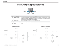
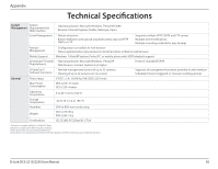
Appendix DI/DO Input Specifications DC Power 5V N.C / N.O Pin 1 Pin 2 Pin 4 Pin 3 PIN FUNCTION 1 Digital Out (DO) 2 Digital In (DI) 3 DC5V OUTPUT 4 GND NOTE Uses an open-drain NFET transistor with the source connected to GND in camera. If used with an external relay, a diode must be connected in parallel with the load for protection against voltage transients. Max loading is 100 mA. A switch from DI to DC 5 V, activated by setting NO. or NC. DC 5 V Output / Max. 100 mA GND Internal 5V Power DND 5V DI 100 mA DO Reed switch R Diode DC Power 5V N.C / N.O External 3~12V Power DND 5V DC Power 3V~12V DI 100 mA DO Reed switch R Diode ALARM D-Link DCS-2210/2230 User Manual ALARM 56
-
 1
1 -
2
-
3
-
4
-
5
-
6
-
7
-
8
-
9
-
10
-
11
-
12
-
13
-
14
-
15
-
16
-
17
-
18
-
19
-
20
-
21
-
22
-
23
-
24
-
25
-
26
-
27
-
28
-
29
-
30
-
31
-
32
-
33
-
34
-
35
-
36
-
37
-
38
-
39
-
40
-
41
-
42
-
43
-
44
-
45
-
46
-
47
-
48
-
49
-
50
-
 51
51 -
 52
52 -
 53
53 -
 54
54 -
 55
55 -
 56
56 -
 57
57 -
 58
58 -
 59
59 -
 60
60 -
 61
61 -
62
-
63
-
64
-
65
-
66
-
67
 |
 |

56
D-Link DCS-2210/2230 User Manual
Appendix
DI/DO Input Specifications
Appendix
Pin 1
Pin 4
Pin 3
Pin 2
PIN
FUNCTION
NOTE
1
Digital Out (DO)
Uses an open-drain NFET transistor with the source connected to GND in camera. If used
with an external relay, a diode must be connected in parallel with the load for protection
against voltage transients. Max loading is 100 mA.
2
Digital In (DI)
A switch from DI to DC 5 V, activated by setting NO. or NC.
3
DC5V OUTPUT
DC 5 V Output / Max. 100 mA
4
GND
GND
Internal 5V Power
External 3~12V Power
DO
DI
5V
DND
N.C
/
N.O
100 mA
ALARM
Reed switch
Diode
DC Power 5V
R
DO
DI
5V
DND
N.C
/
N.O
ALARM
Reed switch
Diode
DC Power 5V
R
DC Power 3V~12V
100 mA