D-Link DES-3326SRM Product Manual - Page 143
VLANs in Layer 2, Layer 3-Based VLANs, Planning VLAN Layout - des review
 |
UPC - 790069255304
View all D-Link DES-3326SRM manuals
Add to My Manuals
Save this manual to your list of manuals |
Page 143 highlights
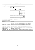
D-Link DES-3326S Layer 3 Switch Chapter 18 VLANS AND IP INTERFACES VLANs can function somewhat differently in a Layer 3 Switch, that is when the VLANs are Layer 3-based, than if they are strictly based on Layer 2 information. Since IP Switching among VLANs may be unfamiliar to users who are otherwise well acquainted with conventional VLANs used in standard Ethernet Switches, some explanation of VLANs used in Layer 3 Switching is presented below. It is essential to fully grasp this difference to take advantage of the improved efficiency of Layer 3 Switching. VLANs in Layer 2 In normal 802.1Q VLAN implementation, packets cannot cross VLANs in a Switch that is limited to Layer 2 functions. If a member of one VLAN wants to connect to another VLAN, the link must be through an external router. Layer 3-Based VLANs Layer 3-based VLANs use network-layer addresses (subnet address for TCP/IP) to determine VLAN membership. These VLANs are based on layer 3 information, however this does not constitute a 'routing' function. The DES-3326S Switch allows an IP subnet to be configured for each 802.1Q VLAN that exists on the Switch. That is, a VLAN can be associated or attached to an IP subnet. This represents an improvement in performance since it bypasses any routing functions, packets transferred between subnets are reduced to a "hardware" decision. Even though a Switch inspects a packet's IP address to determine VLAN membership, no route calculation is performed, the RIP protocol is not employed, and packets traversing the Switch are bridged using the Spanning Tree algorithm. A Switch that implements layer 3 (or 'subnet') VLANs without performing any routing function between these VLANs is referred to as performing 'IP Switching'. Planning VLAN Layout VLANs on the DES-3326S have considerably more functions and are more complex than on a traditional layer 2 Switch, and must therefore be laid-out and configured with a bit more forethought. VLANs with an IP interface assigned to them could be thought of as network links - not just as a collection of associated end users. Further, VLANs assigned an IP network address and subnet mask enables IP routing between them. VLANs must be configured on the Switch before they can be assigned IP subnets. Furthermore, the static VLAN configuration is specified on a per port basis. On the DES-3326S a VLAN can consist of end-nodes - just like a traditional layer 2 Switch, but a VLAN can also consist of one or more Switches - each of which is connected to multiple end-nodes or network resources. So, the IP subnets for a network must be determined first, and the VLANs configured on the Switch to accommodate the IP subnets. Finally, the IP subnets can be assigned to the VLANs. Assigning IP Network Addresses and Subnet Masks to VLANs The DES-3326S allows the assignment of IP subnets to individual VLANs. This is the fundamental advantage of VLANs in IP Switching. Developing an IP addressing scheme is a complex subject, but it is sufficient here to mention that the total number of anticipated end nodes - for each IP interface - must be accommodated with an unique IP address. It should be noted that the Switch regards a VLAN with an IP network address and corresponding subnet mask assigned as an IP interface. Understanding 802.1Q VLANs This review of 802.1Q VLANs presents some basic background about how VLANs work according to the IEEE 802.1Q standard. VLANs operate according to the same rules regardless of whether the Switching environment is Layer 2 or Layer 3. The difference is primarily that in a Layer 3 Switch there is an added capability of unique association between a VLAN and an IP interface or subnet group. A VLAN is a collection of end nodes grouped by logic rather than physical location. End nodes that frequently communicate with each other are assigned to the same VLAN, regardless of where they are located physically on the network. Logically, a 133
-
 1
1 -
2
-
3
-
4
-
5
-
6
-
7
-
8
-
9
-
10
-
11
-
12
-
13
-
14
-
15
-
16
-
17
-
18
-
19
-
20
-
21
-
22
-
23
-
24
-
25
-
26
-
27
-
28
-
29
-
30
-
31
-
32
-
33
-
34
-
35
-
36
-
37
-
38
-
39
-
40
-
41
-
42
-
43
-
44
-
45
-
46
-
47
-
48
-
49
-
50
-
51
-
52
-
53
-
54
-
55
-
56
-
57
-
58
-
59
-
60
-
61
-
62
-
63
-
64
-
65
-
66
-
67
-
68
-
69
-
70
-
71
-
72
-
73
-
74
-
75
-
76
-
77
-
78
-
79
-
80
-
81
-
82
-
83
-
84
-
85
-
86
-
87
-
88
-
89
-
90
-
91
-
92
-
93
-
94
-
95
-
96
-
97
-
98
-
99
-
100
-
101
-
102
-
103
-
104
-
105
-
106
-
107
-
108
-
109
-
110
-
111
-
112
-
113
-
114
-
115
-
116
-
117
-
118
-
119
-
120
-
121
-
122
-
123
-
124
-
125
-
126
-
127
-
128
-
129
-
130
-
131
-
132
-
133
-
134
-
135
-
136
-
137
-
 138
138 -
 139
139 -
 140
140 -
 141
141 -
 142
142 -
 143
143 -
 144
144 -
 145
145 -
 146
146 -
 147
147 -
 148
148 -
149
-
150
-
151
-
152
-
153
-
154
-
155
-
156
-
157
-
158
-
159
-
160
-
161
-
162
-
163
-
164
-
165
-
166
-
167
-
168
-
169
-
170
-
171
-
172
-
173
-
174
-
175
-
176
-
177
-
178
-
179
-
180
-
181
-
182
-
183
-
184
-
185
-
186
-
187
-
188
-
189
-
190
-
191
-
192
-
193
-
194
-
195
-
196
-
197
-
198
-
199
-
200
-
201
-
202
-
203
-
204
-
205
-
206
-
207
-
208
-
209
-
210
-
211
-
212
-
213
-
214
-
215
-
216
-
217
-
218
-
219
-
220
-
221
-
222
-
223
-
224
-
225
-
226
-
227
-
228
-
229
-
230
-
231
-
232
-
233
-
234
-
235
-
236
-
237
-
238
-
239
-
240
-
241
-
242
 |
 |