D-Link DES-3624 Product Manual - Page 15
Rear Panel, Side Panels - des i
 |
UPC - 790069221736
View all D-Link DES-3624 manuals
Add to My Manuals
Save this manual to your list of manuals |
Page 15 highlights
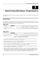
Stackable NWay Ethernet Switch User's Guide Rear Panel The rear panel of the DES-3624, DES-3624F, and DES-3624FM consist of a slot (labeled Slot2) for a Stacking input/output port and an AC power connector. The rear panel of the DES-3624i, DES-3624iF, and DES3624iFM consist of two slots (labeled Slot2 and Slot3). Slot2 is for Stacking input/output ports Sio1, Sio2, and Sio3. Slot3 is for an optional Gigabit Ethernet uplink (MDI-II) port. The following shows the rear panel of the Switches. Figure 3-2. Rear panel view of the Switches ♦ The optional Gigabit Ethernet slide-in module is an uplink/MDI-II (media dependent interface) port for uplink to another Switch (DES-3624i, DES-3624iF, and DES-3624iFM only). Two models are available, one-port and two-port. ♦ The Stacking input/output port slide-in module in the rear panel is for stacking to another device to implement a high-port count, manageable Switch. The three-port module is for a master device and a one-port module is for a client device. ♦ The AC power connector is a three-pronged connector that supports the power cord. Plug in the female connector of the provided power cord into this connector, and the male into a power outlet. Supported input voltages range from 100 ~ 240 VAC at 50 ~ 60 Hz. Side Panels The right side panel of the Switch contains two system fans (see the bottom part of the diagram below). The left side panel contains heat vents. Identifying External Components 19
-
 1
1 -
2
-
3
-
4
-
5
-
6
-
7
-
8
-
9
-
 10
10 -
 11
11 -
 12
12 -
 13
13 -
 14
14 -
 15
15 -
 16
16 -
 17
17 -
 18
18 -
 19
19 -
 20
20 -
21
-
22
-
23
-
24
-
25
-
26
-
27
-
28
-
29
-
30
-
31
-
32
-
33
-
34
-
35
-
36
-
37
-
38
-
39
-
40
-
41
-
42
-
43
-
44
-
45
-
46
-
47
-
48
-
49
-
50
-
51
-
52
-
53
-
54
-
55
-
56
-
57
-
58
-
59
-
60
-
61
-
62
-
63
-
64
-
65
-
66
-
67
-
68
-
69
-
70
-
71
-
72
-
73
-
74
-
75
-
76
-
77
-
78
-
79
-
80
-
81
-
82
-
83
-
84
-
85
-
86
-
87
-
88
-
89
-
90
-
91
-
92
-
93
-
94
-
95
-
96
-
97
-
98
-
99
-
100
-
101
-
102
-
103
-
104
-
105
-
106
-
107
-
108
-
109
-
110
-
111
-
112
-
113
-
114
-
115
-
116
-
117
-
118
-
119
-
120
-
121
-
122
-
123
-
124
-
125
-
126
-
127
-
128
-
129
-
130
-
131
-
132
-
133
-
134
-
135
-
136
-
137
-
138
-
139
-
140
-
141
-
142
-
143
-
144
-
145
-
146
-
147
-
148
-
149
-
150
-
151
-
152
-
153
-
154
-
155
-
156
-
157
-
158
-
159
-
160
-
161
-
162
-
163
-
164
-
165
-
166
-
167
-
168
-
169
-
170
-
171
-
172
-
173
-
174
-
175
 |
 |
