D-Link DES-3624 Product Manual - Page 21
LED Indicators, The Switch LED indicators
 |
UPC - 790069221736
View all D-Link DES-3624 manuals
Add to My Manuals
Save this manual to your list of manuals |
Page 21 highlights
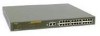
Stackable NWay Ethernet Switch User's Guide LED Indicators The LED indicators of the Switch include Power, Console, Slot, Giga, Speed, and Link/Act. The following shows the LED indicators for the Switch along with an explanation of each indicator. Figure 3-12. The Switch LED indicators ♦ Power This indicator on the front panel should light green after approximately 2 seconds to indicate the ready state of the Switch when the device is powered on. The LED will blink when the Power-On Self-Test (POST) is running or if the system's configuration has changed. This LED will light orange when an error occurs. ♦ Console This indicator is lit green when the switch is being managed via out-of-band/local console management through the RS-232 console port using a straight-through serial cable. When a secured connection is established, this LED is lit. The indicator blinks when the console RS-232 is accessed. ♦ Slot2 This indicator is lit green when a slide-in module is present in the rear panel of the Switch. ♦ Slot3 This indicator is lit green when a slide-in module is present in the rear panel of the Switch. ♦ Giga1 This indicator is lit green when a link is established. It blinks green when the Gigabit port is active. ♦ Giga2 This indicator is lit green when a link is established. It blinks green when the Gigabit port is active. ♦ Sio1 This indicator is lit green when a Stacking IO port is present in the rear panel of the Switch. ♦ Sio2 This indicator is lit green when a Stacking IO port is present in the rear panel of the Switch. ♦ Sio3 This indicator is lit green when a Stacking IO port is present in the rear panel of the Switch. Identifying External Components 25
-
 1
1 -
2
-
3
-
4
-
5
-
6
-
7
-
8
-
9
-
10
-
11
-
12
-
13
-
14
-
15
-
 16
16 -
 17
17 -
 18
18 -
 19
19 -
 20
20 -
 21
21 -
 22
22 -
 23
23 -
 24
24 -
 25
25 -
 26
26 -
27
-
28
-
29
-
30
-
31
-
32
-
33
-
34
-
35
-
36
-
37
-
38
-
39
-
40
-
41
-
42
-
43
-
44
-
45
-
46
-
47
-
48
-
49
-
50
-
51
-
52
-
53
-
54
-
55
-
56
-
57
-
58
-
59
-
60
-
61
-
62
-
63
-
64
-
65
-
66
-
67
-
68
-
69
-
70
-
71
-
72
-
73
-
74
-
75
-
76
-
77
-
78
-
79
-
80
-
81
-
82
-
83
-
84
-
85
-
86
-
87
-
88
-
89
-
90
-
91
-
92
-
93
-
94
-
95
-
96
-
97
-
98
-
99
-
100
-
101
-
102
-
103
-
104
-
105
-
106
-
107
-
108
-
109
-
110
-
111
-
112
-
113
-
114
-
115
-
116
-
117
-
118
-
119
-
120
-
121
-
122
-
123
-
124
-
125
-
126
-
127
-
128
-
129
-
130
-
131
-
132
-
133
-
134
-
135
-
136
-
137
-
138
-
139
-
140
-
141
-
142
-
143
-
144
-
145
-
146
-
147
-
148
-
149
-
150
-
151
-
152
-
153
-
154
-
155
-
156
-
157
-
158
-
159
-
160
-
161
-
162
-
163
-
164
-
165
-
166
-
167
-
168
-
169
-
170
-
171
-
172
-
173
-
174
-
175
 |
 |
