D-Link DGS-1510-28P User Manual - Page 15
Rear Panel Components, Power, Console, Link/Act LEDs, Copper Ports, SFP Ports, DGS-1510-28P, Stack ID
 |
View all D-Link DGS-1510-28P manuals
Add to My Manuals
Save this manual to your list of manuals |
Page 15 highlights
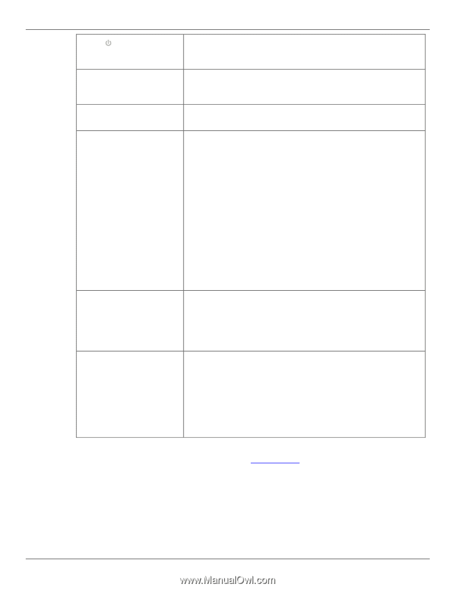
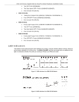
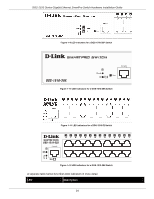
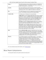
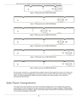
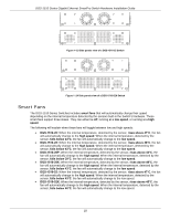
DGS-1510 Series Gigabit Ethernet SmartPro Switch Hardware Installation Guide Power Console This LED will light green after powering the Switch on to indicate the ready state of the device. The indicator is dark when the Switch is no longer receiving power (i.e. powered off). This LED will blink green during the Power-On Self Test (POST). When the POST is finished, the LED goes dark. The indicator will light steady green when a user is logged in through the console port. Fan This LED will light green after the diagnostics have passed with no errors. This LED blinks red when any of the fans has failed. Link/Act LEDs The Switch has LED indicators for Link and Activity. Copper Ports: The LED will light steady green when there is a secure connection (or link) to a 1000Mbps Ethernet device or steady orange when there is a secure connection (or link) to a 10/100Mbps Ethernet device at any of the copper ports. The LED will blink green when a 1000Mbps port is active or blink orange when a 10/100Mbps port is active. The LED remains dark when there is no link or activity. SFP Ports: The LED will light steady green when there is a secure connection (or link) to a 1000Mbps Ethernet device at any of the SFP ports. The LED remains dark when there is no link or activity. SFP+ Ports: The LED will light steady green when there is a secure connection (or link) to a 10Gbps Ethernet device or steady orange when there is a secure connection (or link) to a 1Gbps Ethernet device at any of the SFP+ ports. The LED will blink green when a 10Gbps port is active or blink orange when a 1Gbps port is active. The LED remains dark when there is no link or activity. PoE Stack ID Only the DGS-1510-28P switches are equipt with a PoE LED. When this light is on with a solid green light, it means that the corresponding ports are feeding power to the PoE devices plugged in. When this light is on with a solid orange light, it means that the port is in an error condition state. When this light is off, it means that the ports are not supplying power to the devices plugged into the ports. For standalone Switches, this will display number "1". For stacked Switches, this indicates the position in the stacking box ID. The box ID is assigned either by the user (static mode) or by the system (automatic mode). When "1" to "6" is displayed, this indicates the stacking position of the switch. An "H" indicates the device was assigned as the stacking Master. "h" means the device was selected to be the Backup Master. A "G" is displayed when the Safeguard Engine feature enters the exhausted mode. An "E" is displayed when an error was found during the system self-test. For more information about LED Indicators, refer to LED Indicators. Rear Panel Components The rear panel contains an AC power socket and a security lock. 15
-
 1
1 -
2
-
3
-
4
-
5
-
6
-
7
-
8
-
9
-
 10
10 -
 11
11 -
 12
12 -
 13
13 -
 14
14 -
 15
15 -
 16
16 -
 17
17 -
 18
18 -
 19
19 -
 20
20 -
21
-
22
-
23
-
24
-
25
-
26
-
27
-
28
-
29
-
30
-
31
-
32
-
33
-
34
-
35
-
36
-
37
-
38
-
39
-
40
-
41
-
42
-
43
-
44
-
45
-
46
-
47
-
48
-
49
-
50
-
51
-
52
-
53
-
54
-
55
-
56
-
57
-
58
-
59
-
60
-
61
-
62
-
63
-
64
 |
 |