D-Link DGS-1510-28P User Manual - Page 16
Side Panel Components, 240 VAC at 50~60 Hz. - 52
 |
View all D-Link DGS-1510-28P manuals
Add to My Manuals
Save this manual to your list of manuals |
Page 16 highlights
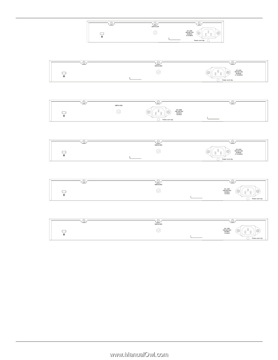
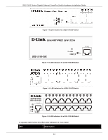
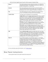
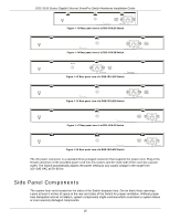
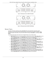
DGS-1510 Series Gigabit Ethernet SmartPro Switch Hardware Installation Guide Figure 1-13 Rear panel view of a DGS-1510-20 Switch Figure 1-14 Rear panel view of a DGS-1510-28 Switch Figure 1-15 Rear panel view of a DGS-1510-28P Switch Figure 1-16 Rear panel view of a DGS-1510-28X Switch Figure 1-17 Rear panel view of a DGS-1510-52 Switch Figure 1-18 Rear panel view of a DGS-1510-52X Switch The AC power connector is a standard three-pronged connector that supports the power cord. Plug-in the female connector of the provided power cord into this socket, and the male side of the cord into a power outlet. The Switch automatically adjusts the power setting to any supply voltage in the range from 100~240 VAC at 50~60 Hz. Side Panel Components The system heat vents located on the sides of the Switch dissipate heat. Do not block these openings. Leave at least 6 inches of space at the rear and sides of the Switch for proper ventilation. Without proper heat dissipation and air circulation, system components might overheat which could lead to system failure or even severely damaged components. 16
-
 1
1 -
2
-
3
-
4
-
5
-
6
-
7
-
8
-
9
-
10
-
 11
11 -
 12
12 -
 13
13 -
 14
14 -
 15
15 -
 16
16 -
 17
17 -
 18
18 -
 19
19 -
 20
20 -
 21
21 -
22
-
23
-
24
-
25
-
26
-
27
-
28
-
29
-
30
-
31
-
32
-
33
-
34
-
35
-
36
-
37
-
38
-
39
-
40
-
41
-
42
-
43
-
44
-
45
-
46
-
47
-
48
-
49
-
50
-
51
-
52
-
53
-
54
-
55
-
56
-
57
-
58
-
59
-
60
-
61
-
62
-
63
-
64
 |
 |