D-Link DGS-1510-28P User Manual - Page 46
Appendix B – Cables and Connectors, Ethernet Cable
 |
View all D-Link DGS-1510-28P manuals
Add to My Manuals
Save this manual to your list of manuals |
Page 46 highlights
DGS-1510 Series Gigabit Ethernet SmartPro Switch Hardware Installation Guide Appendix B - Cables and Connectors Ethernet Cable When connecting the Switch to another switch, a bridge or hub, a normal cable is necessary. Please review these products for matching cable pin assignment. The following diagrams and tables show the standard RJ-45 connector and their pin assignments. RJ-45 PIN Assignments: Pin 1 2 3 4 5 6 7 8 Figure B-1 Standard RJ-45 port and connector MDI-X Port RD+ (receive) RD- (receive) TD+ (transmit) 1000BASE-T 1000BASE-T TD- (transmit) 1000BASE-T 1000BASE-T MDI-II Port TD+ (transmit) TD- (transmit) RD+ (receive) 1000BASE-T 1000BASE-T RD- (receive) 1000BASE-T 1000BASE-T 46
-
 1
1 -
2
-
3
-
4
-
5
-
6
-
7
-
8
-
9
-
10
-
11
-
12
-
13
-
14
-
15
-
16
-
17
-
18
-
19
-
20
-
21
-
22
-
23
-
24
-
25
-
26
-
27
-
28
-
29
-
30
-
31
-
32
-
33
-
34
-
35
-
36
-
37
-
38
-
39
-
40
-
 41
41 -
 42
42 -
 43
43 -
 44
44 -
 45
45 -
 46
46 -
 47
47 -
 48
48 -
 49
49 -
 50
50 -
 51
51 -
52
-
53
-
54
-
55
-
56
-
57
-
58
-
59
-
60
-
61
-
62
-
63
-
64
 |
 |
DGS-1510 Series Gigabit Ethernet SmartPro Switch Hardware Installation Guide
46
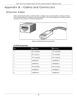
Appendix B – Cables and Connectors
Ethernet Cable
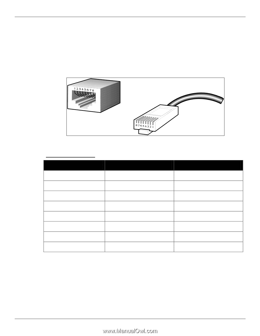
When connecting the Switch to another switch, a bridge or hub, a normal cable is necessary. Please
review these products for matching cable pin assignment. The following diagrams and tables show the
standard RJ-45 connector and their pin assignments.
Figure B–1 Standard RJ-45 port and connector
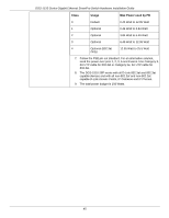
RJ-45 PIN Assignments:
Pin
MDI-X Port
MDI-II Port
1
RD+ (receive)
TD+ (transmit)
2
RD- (receive)
TD- (transmit)
3
TD+ (transmit)
RD+ (receive)
4
1000BASE-T
1000BASE-T
5
1000BASE-T
1000BASE-T
6
TD- (transmit)
RD- (receive)
7
1000BASE-T
1000BASE-T
8
1000BASE-T
1000BASE-T