Dell 2330d Service Manual - Page 48
Service checks, Controller board service check
 |
UPC - 884116003618
View all Dell 2330d manuals
Add to My Manuals
Save this manual to your list of manuals |
Page 48 highlights
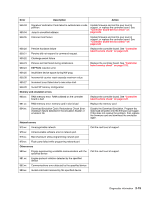
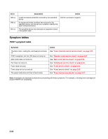
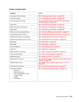
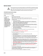
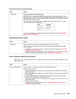
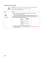
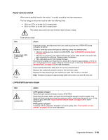
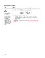
Service checks Service checks which involve measuring voltages on the LVPS/HVPS (low voltage power supply/ high voltage power supply board) should be performed with the printer positioned on its back side. Note: When making voltage readings, always use frame ground unless another ground is specified. See the wiring diagram in the back of the book for more information. Controller board service check Controller board service check FRU Action Controller board assembly Warning: Do not replace the operator panel and controller board at the same time. Each card contains the printer settings. When either of these cards is new, it obtains some of the settings from the other card. Settings are lost when both are new and replaced at the same time. POST (Power-On Self Test) Note: The printer should complete POST in approximately 30 seconds. If the printer fails to display lights or activate the drive motor, fuser, or fan, then check the following in order: 1. Power to the LVPS/HVPS Turn the printer on and listen carefully for a click near the switch. A clicking sound verifies that the outlet and power cables are good. Absence of a clicking sound may indicate a lack of power supplied to the LVPS/HVPS. 2. Power from the LVPS/HVPS to the controller board With the power on, check the LED below the right lower corner of the fan. If the LED lights up, it indicates that power is supplied to the controller board. If the LED does not light up, proceed to the next check item. 3. Cables correctly plugged, especially for the operator panel The printer will not power-up without a functioning operator panel even with a lighted LED on the controller board. 4. The controller board assembly The LED adjacent to J12 will be illuminated if the card is powered and good. 5. The operator panel See "Operator panel service check" on page 2-27. Verify +24 V dc input from the LVPS/HVPS. 1. Turn the printer off. 2. Disconnect the LVPS/HVPS cable from the controller board at J502. 3. Turn the printer on. 4. Verify +24 V dc on positions 6, 17, and 19 of the cable connector (LVPS/HVPS). If there is no voltage supplied on any of these positions, turn the printer off and go to step 7. 5. Verify +5 V dc on positions 1, 3, 4, 5, 11, 13 and 15 of the cable connector (LVPS/ HVPS). If there is no voltage supplied on any of these positions, turn the printer off and go to step 7. 6. Turn the printer off. Check the continuity of the conductors of the cable and the card connector with respect to ground. Verify that pins 10, 12, 14, 16 and 18 on the cable are grounded. Verify the same pins on the card connector side are grounded too. If there is no continuity on any of the card pins, verify that all the mounting screws are tight. If there is still no connection to ground then replace the controller board. See "Controller board removal" on page 3-6. 7. Open the LVPS/HVPS and disconnect the controller board-to-LVPS/HVPS cable at CN201.Verify continuity in each conductor of the cable. This cable is not a replaceable part. If continuity is still not good then go to "Dead machine service check" on page 3-24. Controller board voltage outputs Turn the printer off, and plug the LVPS/HVPS cable into J502 of the controller board. See the wiring diagram at the end of the manual which identifies the output voltages and grounds for a good controller board. Turn the printer off before plugging or unplugging any connectors. 2-22
-
 1
1 -
2
-
3
-
4
-
5
-
6
-
7
-
8
-
9
-
10
-
11
-
12
-
13
-
14
-
15
-
16
-
17
-
18
-
19
-
20
-
21
-
22
-
23
-
24
-
25
-
26
-
27
-
28
-
29
-
30
-
31
-
32
-
33
-
34
-
35
-
36
-
37
-
38
-
39
-
40
-
41
-
42
-
 43
43 -
 44
44 -
 45
45 -
 46
46 -
 47
47 -
 48
48 -
 49
49 -
 50
50 -
 51
51 -
 52
52 -
 53
53 -
54
-
55
-
56
-
57
-
58
-
59
-
60
-
61
-
62
-
63
-
64
-
65
-
66
-
67
-
68
-
69
-
70
-
71
-
72
-
73
-
74
-
75
-
76
-
77
-
78
-
79
-
80
-
81
-
82
-
83
-
84
-
85
-
86
-
87
-
88
-
89
-
90
-
91
-
92
-
93
-
94
-
95
-
96
-
97
-
98
-
99
-
100
-
101
-
102
-
103
-
104
-
105
-
106
-
107
-
108
-
109
-
110
-
111
-
112
-
113
-
114
-
115
-
116
-
117
-
118
-
119
-
120
-
121
-
122
-
123
-
124
-
125
-
126
-
127
-
128
-
129
-
130
-
131
-
132
-
133
-
134
-
135
-
136
-
137
-
138
-
139
-
140
-
141
-
142
-
143
-
144
-
145
-
146
-
147
-
148
-
149
-
150
-
151
-
152
-
153
-
154
-
155
-
156
-
157
-
158
-
159
-
160
-
161
-
162
-
163
-
164
-
165
-
166
-
167
-
168
-
169
-
170
 |
 |