Dell Brocade 6505 Brocade 6505 Hardware Reference Manual - Page 16
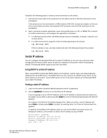
Nonport side of the Brocade 6505
 |
View all Dell Brocade 6505 manuals
Add to My Manuals
Save this manual to your list of manuals |
Page 16 highlights
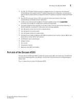
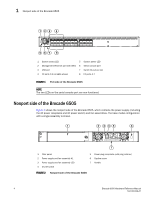
1 Nonport side of the Brocade 6505 123 4 567 8 1 System status LED 5 System power LED 2 Management Ethernet port with LEDs 6 Serial console port 3 USB port 7 Switch ID pull-out tab 4 FC ports 0-3 (all LEDs above) 8 FC ports 4-7 FIGURE 1 Port side of the Brocade 6505 NOTE The two LEDs on the serial console port are non-functional. Nonport side of the Brocade 6505 Figure 2 shows the nonport side of the Brocade 6505, which contains the power supply (including the AC power receptacle and AC power switch) and fan assemblies. The base model configuration with a single assembly is shown. 1 2 345 6 7 1 Filler panel 2 Power supply and fan assembly #1 3 Power supply and fan assembly LED 4 On/off switch 5 Power plug receptacle (with plug retainer) 6 Captive screw 7 Handle FIGURE 2 Nonport side of the Brocade 6505 4 Brocade 6505 Hardware Reference Manual 53-1002449-01
-
 1
1 -
2
-
3
-
4
-
5
-
6
-
7
-
8
-
9
-
10
-
 11
11 -
 12
12 -
 13
13 -
 14
14 -
 15
15 -
 16
16 -
 17
17 -
 18
18 -
 19
19 -
 20
20 -
 21
21 -
22
-
23
-
24
-
25
-
26
-
27
-
28
-
29
-
30
-
31
-
32
-
33
-
34
-
35
-
36
-
37
-
38
-
39
-
40
-
41
-
42
-
43
-
44
-
45
-
46
-
47
-
48
-
49
-
50
-
51
-
52
-
53
-
54
-
55
-
56
-
57
-
58
-
59
-
60
 |
 |
