Dell EqualLogic PS6610E EqualLogic PS6610 Storage Arrays Hardware Owners Manua - Page 11
Back-Panel, Features, Indicators
 |
View all Dell EqualLogic PS6610E manuals
Add to My Manuals
Save this manual to your list of manuals |
Page 11 highlights
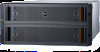
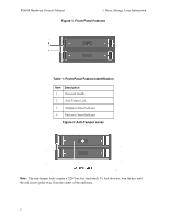
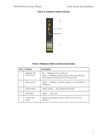
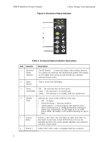
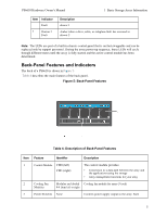
PS6610 Hardware Owner's Manual 1 Basic Storage Array Information Item Indicator Fault 7 Drawer 2 Fault Description drawer 1 Amber when a drive, cable, or sideplane fault has occurred in drawer 2 Note: The LEDs are part of a built-in chassis control panel that is not hot-swappable and can be replaced only by support personnel. During the array power-up sequence, these LEDs will cycle through different states until the array is fully started and the active control module has been determined. Back-Panel Features and Indicators The back of a PS6610 is shown in Figure 5. Table 4 describes the main features of the back panel. Figure 5: Back-Panel Features Table 4: Description of Back-Panel Features Item Feature Identifier Description 1 Control Module CM0 (left) CM1 (right) The control module provides: • Connection to a data path between the array and the applications using the storage • Array management functions for your array 2 Cooling Fan Modules are labeled Cooling fan module for array (5 total) Modules 0-4 from left to right 3 Power Switches None Controls power supply output to the array. Each 5
-
 1
1 -
2
-
3
-
4
-
5
-
 6
6 -
 7
7 -
 8
8 -
 9
9 -
 10
10 -
 11
11 -
 12
12 -
 13
13 -
 14
14 -
 15
15 -
 16
16 -
17
-
18
-
19
-
20
-
21
-
22
-
23
-
24
-
25
-
26
-
27
-
28
-
29
-
30
-
31
-
32
-
33
-
34
-
35
-
36
-
37
-
38
-
39
-
40
-
41
-
42
-
43
-
44
-
45
-
46
-
47
-
48
-
49
-
50
 |
 |
