Dell EqualLogic PS6610E EqualLogic PS6610 Storage Arrays Hardware Owners Manua - Page 30
Correct, Control, Module, Orientation, Installing
 |
View all Dell EqualLogic PS6610E manuals
Add to My Manuals
Save this manual to your list of manuals |
Page 30 highlights
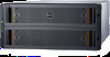
PS6610 Hardware Owner's Manual 3 Control Module Maintenance Figure 15: Correct Control Module Orientation 1. Attach an electrostatic wrist strap or similar protective device. See Hardware Protection on page 6. 2. Pull up on the orange release tab (callout 2 in Figure 16) and swing the lever out. 3. Slide the control module (callout 1 in Figure 16) into the chassis until it is even with the installed controller. The lever should swing smoothly until it is in the locked position. Figure 16: Installing a Control Module 4. Rotate the lever inward, which pushes the control module completely into the slot. The latch on the lever will snap into place. 5. Connect all cables (network and serial port). 6. If the array was shut down, turn on power to the array. 7. Make sure the control module is operational. See Interpreting Control Module LEDs on page 16. The Type 18 control module contains an integral battery assembly used in the cache-to-flash feature of the control module. If the Group Manager GUI or CLI indicates a battery failure, the battery must be replaced. 24
-
 1
1 -
2
-
3
-
4
-
5
-
6
-
7
-
8
-
9
-
10
-
11
-
12
-
13
-
14
-
15
-
16
-
17
-
18
-
19
-
20
-
21
-
22
-
23
-
24
-
 25
25 -
 26
26 -
 27
27 -
 28
28 -
 29
29 -
 30
30 -
 31
31 -
 32
32 -
 33
33 -
 34
34 -
 35
35 -
36
-
37
-
38
-
39
-
40
-
41
-
42
-
43
-
44
-
45
-
46
-
47
-
48
-
49
-
50
 |
 |
