Dell FC4 Brocade 5000 Hardware Reference - Page 19
Connecting to the Switch Using the Serial Connection, Setting the Switch IP Address, Bits per second
 |
View all Dell FC4 Brocade 5000 manuals
Add to My Manuals
Save this manual to your list of manuals |
Page 19 highlights
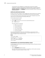
Configuring the Brocade 5000 2 1. Remove the plug from the serial port and insert the serial cable provided with the Brocade 5000. 2. Connect the serial cable to the serial port on the switch and to a serial port on the workstation. 3. Disable any serial communication programs running on the workstation. 4. Open a terminal emulator application (such as HyperTerminal for Windows or TERM in a UNIX environment) and configure the application as follows: - In a Windows 95, 98, 2000, or NT environment: Bits per second: 9600 Databits: 8 Parity: None Stop bits: 1 Flow control: None - In a UNIX environment, enter the following string at the prompt: tip /dev/ttyyb -9600 Connecting to the Switch Using the Serial Connection To log in to the switch through the serial connection: 1. Verify that the switch has completed POST. When POST is complete, the port status and switch power and status LEDs return to a standard healthy state; for information about LED signals, refer to "Interpreting LED Activity" on page 15. 2. When the terminal emulator application stops reporting information, press Enter to display the login prompt. Setting the Switch IP Address To replace the default IP address and related information: 1. Enter the ipAddrSet command at the terminal emulator application prompt, and enter the requested information at the prompts: switch:admin> ipaddrset Ethernet IP Address [10.77.77.77]:10.32.53.47 Ethernet Subnetmask [255.0.0.0]:255.255.240.0 Fibre Channel IP Address [0.0.0.0]: Fibre Channel Subnetmask [0.0.0.0]: Gateway IP Address [0.0.0.0]:10.32.48.1 Set IP address now? [y = set now, n = next reboot]:y IP address being changed... Committing configuration...Done. switch:admin> 2. Optionally, verify that the address was correctly set by typing the ipAddrShow command at the prompt. 3. Record the IP address on the pull out tab (see Figure 1 on page 2) provided for this purpose on the bottom, port side of the Brocade 5000. Brocade 5000 Hardware Reference Manual 9 Publication Number: 53-1000424-03
-
 1
1 -
2
-
3
-
4
-
5
-
6
-
7
-
8
-
9
-
10
-
11
-
12
-
13
-
 14
14 -
 15
15 -
 16
16 -
 17
17 -
 18
18 -
 19
19 -
 20
20 -
 21
21 -
 22
22 -
 23
23 -
 24
24 -
25
-
26
-
27
-
28
-
29
-
30
-
31
-
32
-
33
-
34
-
35
-
36
-
37
-
38
-
39
-
40
-
41
-
42
-
43
-
44
-
45
-
46
-
47
-
48
-
49
-
50
 |
 |