Dell FC4 Brocade 5000 Hardware Reference - Page 30
Field Replaceable Units FRUs, In Advanced Web Tools, click
 |
View all Dell FC4 Brocade 5000 manuals
Add to My Manuals
Save this manual to your list of manuals |
Page 30 highlights
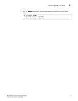
3 Maintaining the Brocade 5000 For information about specific diagnostic tests, refer to the Brocade Fabric OS Administrator's Guide. Field Replaceable Units (FRUs) The power supplies have the fans inside and can be replaced onsite without the use of special tools. The power supplies/fan assemblies units are keyed to ensure correct orientation during installation. Replacement instructions are provided with all replacement units ordered. CAUTION The Brocade 5000 has two power cords. To remove all power from the switch, disconnect both power cords before servicing. Power Supply/Fan Assembly FRU Replacement The Brocade 5000 fans are fixed inside the integrated power supply/fan FRU to provide necessary airflow to cool the whole system. There is one fan located in the rear section of each FRU. The system software sets fan speed and measures their speeds through the tachometer interface. The two power supply/fan assembly FRU units are hot-swappable if replaced one at a time. They are identical and fit into either slot. Fabric OS identifies the power supplies as follows (viewing the switch from the port side): - Power supply #1 is on the left - Power supply #2 is on the right Any of the following methods can be used to determine whether a power supply requires replacing: - Check the power supply status LED next to the I/O switch. If the power supply status LED is not on, verify that the power supply is on and seated and the power cord is connected to a functioning power source. If the light does not turn green, the power supply needs to be replaced. - In Advanced Web Tools, click the Power Status icon. - Type the psShow command at the command prompt to display power supply status as shown below: switch:admin> psshow Power Supply #1 is OK Power Supply #2 is OK To determine whether a fan assembly requires replacing , do any of the following: - Check the system status LED (see Figure 3 on page 3-16 for location of system status LED). If the system status LED is flashing amber and green, it could mean the fan has failed. Check the management interface and the error log for details on the cause of status. - In Advanced Web Tools, check the Fan Status icon background color. It will be either yellow or red if the fan has failed. When the fan is functioning correctly, the background color is green. 20 Brocade 5000 Hardware Reference Manual Publication Number: 53-1000424-03
-
 1
1 -
2
-
3
-
4
-
5
-
6
-
7
-
8
-
9
-
10
-
11
-
12
-
13
-
14
-
15
-
16
-
17
-
18
-
19
-
20
-
21
-
22
-
23
-
24
-
 25
25 -
 26
26 -
 27
27 -
 28
28 -
 29
29 -
 30
30 -
 31
31 -
 32
32 -
 33
33 -
 34
34 -
 35
35 -
36
-
37
-
38
-
39
-
40
-
41
-
42
-
43
-
44
-
45
-
46
-
47
-
48
-
49
-
50
 |
 |
