Dell Force10 C300 Installing and Maintaining the C150 System - Page 18
Line Cards, Blank Panels, Table 5-1., RPM Front Panel and LED Descriptions - lc cb 10ge 8p
 |
View all Dell Force10 C300 manuals
Add to My Manuals
Save this manual to your list of manuals |
Page 18 highlights
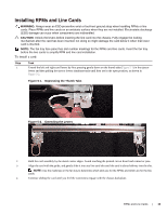
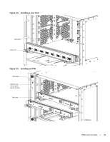
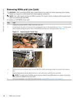
www.dell.com | support.dell.com Table 5-1. RPM Front Panel and LED Descriptions (continued) Section Alarm LED Flash Label Slot In Use LED Master LED Reset Button SFM Active Status LED Description Red: Major Alarm-a critical condition exists (such as a severe over-temperature condition). See Appendix , Alarms, on page 51 for more information. Flashing red: Minor Alarm-a serious condition exists (such as a single fan failure or a line card failure). See Appendix , Alarms, on page 51 for more information. Unlit: No alarm conditions. Use the compact flash card (external compact flash memory card) slot to store and retrieve boot and system images. Green: The flash memory card is in the process of a read or write process. Do not remove the flash card when the In Use LED is lit. Unlit: Not in use Indicates that this RPM is the Primary RPM Green: Primary Unlit: Secondary/ fatal error/ booting Use this recessed reset switch to reset the RPM by inserting a small object, such as a pen tip, to depress the button. Green: Switch Fabric is active Unlit: Switch Fabric is inactive Green: Operational Red: Card problem state Flashing green: Booting/ diagnostics Unlit: In standby mode, or power is off Line Cards Line cards are hot-swappable. Any line card can be inserted into any line card slot. Line card slots are numbered 0 to 3; the number label is on the fan tray. The LC-CB-GE-48P and LC-CB-10GE-8P line cards can only be installed in a chassis running FTOS version 7.6.1.0 or later. NOTE: The LC-CB-GE-48P and LC-CB-10GE-8P line cards are interchangeable between the C300 and C150 only if the chassis is running FTOS version 7.6.1.0 or later. Line card LEDs are described in the documentation specific to each line card. Refer to the installation documentation that came with the card for to understand LED appearance and meaning. Blank Panels Blanks are required in empty slots to control airflow for adequate system cooling, personal safety, and EMI containment during operation. The blank panels do not have board components or connector pins. Align the blank with the guides and gently slide toward the backplane (Figure 5-5 and Figure 5-6). NOTE: All chassis slots must be installed with operational modules or blanks. Always replace cards and blank panels immediately. 18 | RPMs and Line Cards
-
 1
1 -
2
-
3
-
4
-
5
-
6
-
7
-
8
-
9
-
10
-
11
-
12
-
 13
13 -
 14
14 -
 15
15 -
 16
16 -
 17
17 -
 18
18 -
 19
19 -
 20
20 -
 21
21 -
 22
22 -
 23
23 -
24
-
25
-
26
-
27
-
28
-
29
-
30
-
31
-
32
-
33
-
34
-
35
-
36
-
37
-
38
-
39
-
40
-
41
-
42
-
43
-
44
-
45
-
46
-
47
-
48
-
49
-
50
-
51
-
52
-
53
-
54
-
55
-
56
-
57
-
58
-
59
-
60
-
61
-
62
-
63
-
64
-
65
-
66
 |
 |
