Dell Force10 C300 Installing and Maintaining the C150 System - Page 29
Installing DC Power Entry Modules, Recommended Normal Operating Conditions, Redundancy
 |
View all Dell Force10 C300 manuals
Add to My Manuals
Save this manual to your list of manuals |
Page 29 highlights
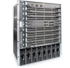
8 Installing DC Power Entry Modules The C150 has six power supply slots at the front-bottom of the chassis (Figure 8-2). The slots accept either AC power supplies (PSUs) or DC Power Entry Modules (PEMs). Dell Force10 does not support the use of a combination of AC and DC. • If you select DC, the C150 requires at least one DC PEM for operation, but Dell Force10 recommends a one-plus-one redundancy configuration. Those DC PEMs are inserted in slots 0 and 2. • To protect against high-voltage shock, install a power supply blank (CC-C-BLNK-PWR) on all unused power supply slots. NOTE: The C150 DC Power Entry Module does not support PoE line cards. Recommended Normal Operating Conditions Table 8-1. Input voltage Input Ranges -44V (minimum) -48V (typical) -55V (maximum) Maximum Power 1408 watts 1536 watts 1760 watts Table 8-2. Operating Ranges Ambient Temperature Operating Range Storage Range Humidity Operating Range Storage Range -5° C to +40° C -40° C to +70 ° C 5-85% RH 5-90% RH Redundancy For full facility redundancy, install two DC PEMs. Each PEM must be attached to an independent power source with a dedicated circuit breaker sized in accordance with your local building and electrical safety codes. Cable and Connector Requirements You must provide your own cables to connect to a remote power source (a circuit breaker panel, for example) in your equipment rack or facility. Cables must be sized to meet the following criteria: Installing DC Power Entry Modules | 29
-
 1
1 -
2
-
3
-
4
-
5
-
6
-
7
-
8
-
9
-
10
-
11
-
12
-
13
-
14
-
15
-
16
-
17
-
18
-
19
-
20
-
21
-
22
-
23
-
 24
24 -
 25
25 -
 26
26 -
 27
27 -
 28
28 -
 29
29 -
 30
30 -
 31
31 -
 32
32 -
 33
33 -
 34
34 -
35
-
36
-
37
-
38
-
39
-
40
-
41
-
42
-
43
-
44
-
45
-
46
-
47
-
48
-
49
-
50
-
51
-
52
-
53
-
54
-
55
-
56
-
57
-
58
-
59
-
60
-
61
-
62
-
63
-
64
-
65
-
66
 |
 |
