Dell Force10 C300 Installing and Maintaining the C150 System - Page 22
Removing RPMs and Line Cards, WARNING, Depressing the Thumb Tabs, Extending the Levers
 |
View all Dell Force10 C300 manuals
Add to My Manuals
Save this manual to your list of manuals |
Page 22 highlights
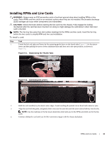
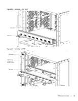
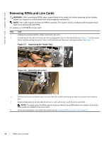
www.dell.com | support.dell.com Removing RPMs and Line Cards WARNING: After removing an RPM, place a panel blank in the empty slot before powering up the chassis. Blanks are required to control airflow and electromagnetic interference. NOTE: The C150 requires at least one RPM to operate. The system enters a software-defined power-down state if you remove the only RPM. To remove a C150 RPM or line card: Step Task 1 Unplug any network interface cables connected to the card. 2 Extend the left and right card levers by first pressing gently down on the thumb tabs (see Figure 5-7) in the ejector levers and then pulling the ejector levers simultaneously until they are in the open position. See Figure 5-8. Figure 5-7. Depressing the Thumb Tabs Figure 5-8. Extending the Levers 3 Pull the card by the card levers until it is out of the slot. Avoid touching the printed circuit board and connector pins. 4 Install a blank panel in all slots that do not have a card, and secure it with the screws provided. NOTE: The blank panels for RPMs and line cards are different sizes (RPM blanks are smaller); be sure that blank panels are installed in the correct slots. 5 If you are replacing the card, follow the instructions in Installing RPMs and Line Cards on page 19. 22 | RPMs and Line Cards
-
 1
1 -
2
-
3
-
4
-
5
-
6
-
7
-
8
-
9
-
10
-
11
-
12
-
13
-
14
-
15
-
16
-
 17
17 -
 18
18 -
 19
19 -
 20
20 -
 21
21 -
 22
22 -
 23
23 -
 24
24 -
 25
25 -
 26
26 -
 27
27 -
28
-
29
-
30
-
31
-
32
-
33
-
34
-
35
-
36
-
37
-
38
-
39
-
40
-
41
-
42
-
43
-
44
-
45
-
46
-
47
-
48
-
49
-
50
-
51
-
52
-
53
-
54
-
55
-
56
-
57
-
58
-
59
-
60
-
61
-
62
-
63
-
64
-
65
-
66
 |
 |
