Dell Force10 C300 Installing and Maintaining the C150 System - Page 19
Installing RPMs and Line Cards, WARNING, CAUTION, Depressing the Thumb Tabs
 |
View all Dell Force10 C300 manuals
Add to My Manuals
Save this manual to your list of manuals |
Page 19 highlights
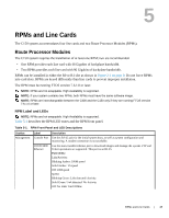
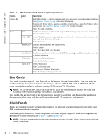
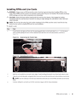
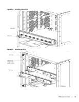
Installing RPMs and Line Cards WARNING: Always wear an ESD-preventive wrist or foot-heel ground strap when handling RPMs or line cards. Place RPMs and line cards on an antistatic surface when they are not installed. Electrostatic discharge (ESD) damage can occur when components are mishandled. CAUTION: Unlock the levers before inserting the line card into the chassis. Fully engage the locking mechanism after the card has been inserted; not doing so might damage the card below it when that lower card is inserted. NOTE: The fan tray face panel has slot number markings for the RPMs and line cards. Insert the fan tray before the line cards to simplify RPM and line card installation. To install a card: Step Task 1 Extend the left and right card levers by first pressing gently down on the thumb tabs (Figure 5-1) in the ejector levers and then pulling the ejector levers simultaneously until they are in the open position, as shown in Figure 5-2. Figure 5-1. Depressing the Thumb Tabs Figure 5-2. Extending the Levers 2 Hold the card assembly by the metal carrier edges. Avoid touching the printed circuit board and connector pins. 3 Align the card with the guide, and gently slide it into any line card slot until the card is about halfway into the slot. NOTE: Use the markings on the fan tray to determine which slots are for the RPMs and which are for the line cards. 4 Continue sliding the card until you feel the connectors engage with the chassis backplane. RPMs and Line Cards | 19
-
 1
1 -
2
-
3
-
4
-
5
-
6
-
7
-
8
-
9
-
10
-
11
-
12
-
13
-
 14
14 -
 15
15 -
 16
16 -
 17
17 -
 18
18 -
 19
19 -
 20
20 -
 21
21 -
 22
22 -
 23
23 -
 24
24 -
25
-
26
-
27
-
28
-
29
-
30
-
31
-
32
-
33
-
34
-
35
-
36
-
37
-
38
-
39
-
40
-
41
-
42
-
43
-
44
-
45
-
46
-
47
-
48
-
49
-
50
-
51
-
52
-
53
-
54
-
55
-
56
-
57
-
58
-
59
-
60
-
61
-
62
-
63
-
64
-
65
-
66
 |
 |
