Dell Inspiron 5400 AIO Inspiron 24-5400 Service Manual
Dell Inspiron 5400 AIO Manual
 |
View all Dell Inspiron 5400 AIO manuals
Add to My Manuals
Save this manual to your list of manuals |
Dell Inspiron 5400 AIO manual content summary:
- Dell Inspiron 5400 AIO | Inspiron 24-5400 Service Manual - Page 1
Inspiron 24-5400 Service Manual Regulatory Model: W24C Regulatory Type: W24C002 September 2020 Rev. A00 - Dell Inspiron 5400 AIO | Inspiron 24-5400 Service Manual - Page 2
of data and tells you how to avoid the problem. WARNING: A WARNING indicates a potential for property damage, personal injury, or death. © 2020 Dell Inc. or its subsidiaries. All rights reserved. Dell, EMC, and other trademarks are trademarks of Dell Inc. or its subsidiaries. Other trademarks may be - Dell Inspiron 5400 AIO | Inspiron 24-5400 Service Manual - Page 3
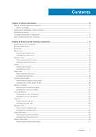
Contents Chapter 1: Safety instructions...6 Before working inside your computer...6 Before you begin ...6 Electrostatic discharge-ESD protection...7 ESD field service kit ...7 Transporting sensitive components...8 After working inside your computer...8 Chapter 2: Removing and installing components - Dell Inspiron 5400 AIO | Inspiron 24-5400 Service Manual - Page 4
BIOS setup program...61 Navigation keys...61 Boot Sequence...61 System setup options...62 Clearing CMOS settings...66 Clearing forgotten passwords...67 Chapter 5: Troubleshooting...69 SupportAssist diagnostics...69 Locate the Service Tag or Express Service Code of your Dell computer 69 4 Contents - Dell Inspiron 5400 AIO | Inspiron 24-5400 Service Manual - Page 5
Display built-in self test...69 Diagnostics...69 Recovering the operating system...70 Flashing BIOS (USB key)...71 Flashing the BIOS...71 Backup media and recovery options...71 WiFi power cycle...71 Flea power release...72 Chapter 6: Getting help and contacting Dell 73 Contents 5 - Dell Inspiron 5400 AIO | Inspiron 24-5400 Service Manual - Page 6
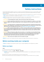
, not by its pins. CAUTION: You should only perform troubleshooting and repairs as authorized or directed by the Dell technical assistance team. Damage due to servicing that is not authorized by Dell is not covered by your warranty. See the safety instructions that shipped with the product or at www - Dell Inspiron 5400 AIO | Inspiron 24-5400 Service Manual - Page 7
problems Dell products, the sensitivity to static damage is now higher than in previous Dell and troubleshoot is service kit The unmonitored Field Service kit is the most commonly used service kit. Each Field Service service properly, service parts can . Use only Field Service kits with a wrist - Dell Inspiron 5400 AIO | Inspiron 24-5400 Service Manual - Page 8
tester, check with your regional office to find out if they have one. To perform the test, plug the wrist-strap's bonding-wire into the service technicians use the traditional wired ESD grounding wrist strap and protective anti-static mat at all times when servicing Dell . 8 Safety instructions - Dell Inspiron 5400 AIO | Inspiron 24-5400 Service Manual - Page 9
2 Removing and installing components NOTE: The images in this document may differ from your computer depending on the configuration you ordered. Inside view of your computer NOTE: The appearance of heat sink differs depending on the graphics configuration you ordered. 1. heat sink 2. fan 3. CMOS - Dell Inspiron 5400 AIO | Inspiron 24-5400 Service Manual - Page 10
● Phillips screwdriver #1 ● Flat-head screwdriver ● Plastic scribe Screw list NOTE: When removing screws from a component, it is recommended to note the screw type, the quantity of screws, and then place them in a screw storage box. This is to ensure that the correct number of screws and correct - Dell Inspiron 5400 AIO | Inspiron 24-5400 Service Manual - Page 11
with the stand hanging over the edge. It is recommended to remove the stand to avoid accidental damage to the computer display during servicing. About this task The following image indicates the location of the back cover and provides a visual representation of the removal procedure. Removing and - Dell Inspiron 5400 AIO | Inspiron 24-5400 Service Manual - Page 12
Steps 1. Place your palm in the middle of the back cover then pry the back cover from the display-assembly base starting from the top corners. 2. Remove the back cover from the display-assembly base. Installing the back cover Prerequisites If you are replacing a component, remove the existing - Dell Inspiron 5400 AIO | Inspiron 24-5400 Service Manual - Page 13
Steps Align the slots on the back cover with the slots on the computer and press along the side to snap the back cover into place. Next steps 1. Follow the procedure in After working inside your computer. Bottom cover Removing the bottom cover Prerequisites 1. Follow the procedure in Before working - Dell Inspiron 5400 AIO | Inspiron 24-5400 Service Manual - Page 14
Steps 1. Remove the five screws (M3x5) that secure the bottom cover to the display-assembly base. 2. Lift the bottom cover off the display-assembly base. Installing the bottom cover Prerequisites If you are replacing a component, remove the existing component before performing the installation - Dell Inspiron 5400 AIO | Inspiron 24-5400 Service Manual - Page 15
surface with the stand hanging over the edge. It is recommended to remove the stand to avoid accidental damage to the computer display during servicing. 2. Remove the back cover. 3. Remove the bottom cover. About this task The following image indicates the location of the stand and provides a visual - Dell Inspiron 5400 AIO | Inspiron 24-5400 Service Manual - Page 16
Steps 1. In the reverse sequential order indicated on the stand, remove the eight screws (M3x4) that secure the stand to the display- assembly base. 2. Remove the stand from the slots on the display-assembly base and lift the stand off the display-assembly base. Installing the stand Prerequisites If - Dell Inspiron 5400 AIO | Inspiron 24-5400 Service Manual - Page 17
Steps 1. Align the screw holes on the stand with the screw holes on the display-assembly base and slide the stand on the display- assembly base. 2. In the sequential order indicated on the stand, replace the eight screws (M3x4) that secure the stand to the display- assembly base. Next steps 1. - Dell Inspiron 5400 AIO | Inspiron 24-5400 Service Manual - Page 18
Steps 1. Remove the two screws (M3x5) that secure the hard-drive assembly to the display-assembly base. 2. Slide the hard-drive assembly away from the hard-drive slot on the display-assembly base. 3. Remove the four screws (M3x3.5) that secure the hard-drive bracket to the hard drive. 4. Remove the - Dell Inspiron 5400 AIO | Inspiron 24-5400 Service Manual - Page 19
Steps 1. Align the screw holes on the hard drive with the screw holes on the hard-drive bracket. 2. Replace the four screws (M3x3.5) that secure the hard-drive bracket to the hard drive. 3. Slide the hard-drive assembly into the slot on the display-assembly base. 4. Replace the two screws (M3x5) - Dell Inspiron 5400 AIO | Inspiron 24-5400 Service Manual - Page 20
Steps 1. Remove the four screws (M3x5) that secure the system-board shield to the display-assembly base. 2. Lift the system-board shield off the display-assembly base. Installing the system-board shield Prerequisites If you are replacing a component, remove the existing component before performing - Dell Inspiron 5400 AIO | Inspiron 24-5400 Service Manual - Page 21
Steps 1. Align the slots on the system-board shield with the ports on the computer. 2. Replace the four screws (M3x5) that secure the system-board shield to the display-assembly base. Next steps 1. Install the stand. 2. Install the bottom cover. 3. Install the back cover. 4. Follow the procedure in - Dell Inspiron 5400 AIO | Inspiron 24-5400 Service Manual - Page 22
Steps 1. Using your fingertips, spread apart the securing clips on the memory-module slot until the memory module pops up. 2. Slide and remove the memory module from the memory-module slot. NOTE: Repeat step 1 and 2 if there are two memory modules. Installing the memory modules Prerequisites If you - Dell Inspiron 5400 AIO | Inspiron 24-5400 Service Manual - Page 23
Steps 1. Align the notch on the memory module with the tab on the memory-module slot. 2. Slide the memory module firmly into the slot at an angle and press the memory module down until it clicks into place. NOTE: If you do not hear the click, remove the memory module and reinstall it. NOTE: Repeat - Dell Inspiron 5400 AIO | Inspiron 24-5400 Service Manual - Page 24
Steps 1. Using your fingertip, press on the metal clip to release the coin-cell battery from the coin-cell battery holder. 2. Lift the coin-cell battery from the coin-cell battery holder. Installing the coin-cell battery Prerequisites If you are replacing a component, remove the existing component - Dell Inspiron 5400 AIO | Inspiron 24-5400 Service Manual - Page 25
Steps With the positive-side facing up, insert the coin-cell battery into the battery socket on the system board and snap the battery into place. Next steps 1. Install the system-board shield. 2. Install the stand. 3. Install the bottom cover. 4. Install the back cover. 5. Follow the procedure in - Dell Inspiron 5400 AIO | Inspiron 24-5400 Service Manual - Page 26
Steps 1. In reverse sequential order (as indicated on the heat sink), loosen the eight captive screws that secure the heat sink to the system board and the display-assembly base. 2. Lift the heat sink off the system board and display-assembly base. Installing the heat sink Prerequisites If you are - Dell Inspiron 5400 AIO | Inspiron 24-5400 Service Manual - Page 27
Steps 1. Align the screw holes on the heat sink with the screw holes on the system board and the display assembly base. 2. In sequential order (as indicated on the heat sink), tighten the eight captive screws that secure the heat sink to the system board and display assembly base. Next steps 1. - Dell Inspiron 5400 AIO | Inspiron 24-5400 Service Manual - Page 28
Steps 1. Remove the two screws (M2x4) that secure the wireless-card shield to the system board. 2. Lift the wireless-card shield off the system board and wireless card. 3. Remove the screw (M2x4) that secures the wireless-card bracket to the wireless card. 4. Slide the wireless-card bracket off the - Dell Inspiron 5400 AIO | Inspiron 24-5400 Service Manual - Page 29
5. Disconnect the antenna cables from the wireless card. 6. Slide and remove the wireless card from the wireless-card slot. Installing the wireless card Prerequisites If you are replacing a component, remove the existing component before performing the installation procedure. CAUTION: To avoid - Dell Inspiron 5400 AIO | Inspiron 24-5400 Service Manual - Page 30
Steps 1. Connect the antenna cables to the wireless card. The following table provides the antenna-cable color scheme for the wireless card supported by your computer. Table 2. Antenna-cable color scheme Connectors on the wireless card Main (white triangle) Antenna-cable color White Auxiliary ( - Dell Inspiron 5400 AIO | Inspiron 24-5400 Service Manual - Page 31
Steps 1. Remove the screw (M2x2.5) that secures the solid-state drive to the system board. 2. Slide and remove the solid-state drive from the M.2 card slot on the system board. Installing the solid-state drive Prerequisites CAUTION: Solid-state drives are fragile. Exercise care when handling the - Dell Inspiron 5400 AIO | Inspiron 24-5400 Service Manual - Page 32
Steps 1. Align the notch on the solid-state drive with the tab on the M.2 card slot. 2. Slide the solid-state drive into the M.2 card slot on the system board. 3. Replace the screw (M2x2.5) that secures the solid-state drive to the system board. Next steps 1. Install the system-board shield. 2. - Dell Inspiron 5400 AIO | Inspiron 24-5400 Service Manual - Page 33
Steps 1. Remove the screw (M2x3) that secure the media-card reader to the display-assembly base. 2. Open the latch and disconnect the media-card reader cable from the system board. 3. Remove the media-card reader from media-card reader slot. Installing the media-card reader Prerequisites If you are - Dell Inspiron 5400 AIO | Inspiron 24-5400 Service Manual - Page 34
Steps 1. Connect the media-card reader cable to the system board and close the latch to secure the cable. 2. Insert the media-card reader into the media-card reader slot. 3. Align the screws on the media-card reader with the screw holes on the slot on the display assembly base. 4. Replace the screw - Dell Inspiron 5400 AIO | Inspiron 24-5400 Service Manual - Page 35
base. 2. Remove the six screws (M3 4+7.1xZN) that secure the speakers to the display-assembly base. 3. Remove the speaker cable from the routing guides on the display-assembly base. 4. Lift the speakers along with the cable off the display-assembly base. Installing the speakers Prerequisites If you - Dell Inspiron 5400 AIO | Inspiron 24-5400 Service Manual - Page 36
base. 2. Replace the eight screws (M3 4+7.1xZN) that secure the speakers to the display-assembly base. 3. Route the speaker cable through the routing guide on display-assembly base and connect the speaker cable to the system board. Next steps 1. Install the system-board shield. 2. Install the stand - Dell Inspiron 5400 AIO | Inspiron 24-5400 Service Manual - Page 37
-assembly base. 2. Remove the eight screws (M2X2.5) that secure the microphone modules (2) to the base panel and release them from the routing guides on the display-assembly base. 3. Lift the microphone modules (2) off the slots on the base panel. Installing the mircrophones Prerequisites If you are - Dell Inspiron 5400 AIO | Inspiron 24-5400 Service Manual - Page 38
base. 3. Replace the eight screws (M2X2.5) that secure the microphone module to the base panel. 4. Route the microphone cable through the routing guides on the display-assembly base and connect the microphone cable to the system board. Next steps 1. Install the speakers. 2. Install the system-board - Dell Inspiron 5400 AIO | Inspiron 24-5400 Service Manual - Page 39
and provides a visual representation of the removal procedure. Steps 1. Disconnect the fan cable from the system board. 2. Remove the fan cable from the routing guides on the display-assembly base. 3. Remove the three screws (M2x2.5) that secure the fan to the display-assembly base. 4. Lift the fan - Dell Inspiron 5400 AIO | Inspiron 24-5400 Service Manual - Page 40
-assembly base. 2. Replace the three screws (M2x2.5) that secure the fan to the display-assembly base. 3. Route the fan cable through the routing guides on the display-assembly base. 4. Connect the fan cable to the system board. Next steps 1. Install the system-board shield. 2. Install the stand - Dell Inspiron 5400 AIO | Inspiron 24-5400 Service Manual - Page 41
the antenna modules printed on the display-assembly base as ANT-B (black) and ANT-W (white). Steps 1. Remove the antenna cables from the routing guides on the display-assembly base. 2. Remove the two screws (M2x2.5) that secure the antenna modules (2) to the base panel. 3. Carefully peel the copper - Dell Inspiron 5400 AIO | Inspiron 24-5400 Service Manual - Page 42
panel. 3. Replace the two screws (M2x2.5) that secure the antenna modules (2) to the base panel. 4. Route the antenna cables through the routing guides on the display-assembly base. Next steps 1. Install the speakers. 2. Install the wireless card. 3. Install the system-board shield. 4. Install the - Dell Inspiron 5400 AIO | Inspiron 24-5400 Service Manual - Page 43
a visual representation of the removal procedure. Steps 1. Disconnect the camera cable from the system board. 2. Remove the camera cable from the routing guides on the display-assembly base. 3. Remove the two screws (M3x5) that secure the retractable-camera assembly to the base panel. 4. Remove the - Dell Inspiron 5400 AIO | Inspiron 24-5400 Service Manual - Page 44
panel. 2. Replace the two screws (M3x5) that secure the retractable-camera assembly to the base panel. 3. Route the camera cable through the routing guides on the display-assembly base. 4. Connect the camera cable to the system board. Next steps 1. Install the system-board shield. 2. Install the - Dell Inspiron 5400 AIO | Inspiron 24-5400 Service Manual - Page 45
Steps 1. Open the notch on the side of the power-button board and lift the power-button board from the slot on the base panel. 2. Open the latch, disconnect the power-button board cable from the power-button board then lift off the power-button board. Installing the power-button board Prerequisites - Dell Inspiron 5400 AIO | Inspiron 24-5400 Service Manual - Page 46
board Removing the system board Prerequisites 1. Follow the procedure in Before working inside your computer. NOTE: Your computer's Service Tag is stored in the system board. You must enter the Service Tag in the BIOS setup program after you replace the system board. NOTE: Replacing the system board - Dell Inspiron 5400 AIO | Inspiron 24-5400 Service Manual - Page 47
7. Remove the wireless card. 8. Remove the solid-state drive. 9. Remove the heat sink. About this task The following image indicates the connectors on your system board. Figure 1. System-board connectors 1. Camera cable 3. Debug port 5. Fan cable 7. Media-card reader cable 9. Power-button board - Dell Inspiron 5400 AIO | Inspiron 24-5400 Service Manual - Page 48
Steps 1. Disconnect the backlit cable from the system board. 2. Disconnect the display cable from the system board. 3. Open the latch and disconnect the power-button board cable from the system board. 4. Disconnect the speaker cable from the system board. 5. Disconnect the media-card reader cable - Dell Inspiron 5400 AIO | Inspiron 24-5400 Service Manual - Page 49
About this task The following image indicates the connectors on your system board. Figure 2. System-board connectors 1. Camera cable 3. Debug port 5. Fan cable 7. Media-card reader cable 9. Power-button board cable 11. Hard-drive connector 13. Backlit cable 2. Touchscreen cable 4. Coin-cell - Dell Inspiron 5400 AIO | Inspiron 24-5400 Service Manual - Page 50
Steps 1. Align the screw holes on the system board with the screw holes on the display-assembly base. 2. Replace the five screws (M3x5) that secure the system board to the display-assembly base. 3. Connect the camera cable to the system board. 4. Connect the touchscreen cable to the system board. 5. - Dell Inspiron 5400 AIO | Inspiron 24-5400 Service Manual - Page 51
cover. 8. Install the back cover. 9. Follow the procedure in After working inside your computer. NOTE: Your computer's Service Tag is stored in the system board. You must enter the Service Tag in the BIOS setup program after you replace the system board. NOTE: Replacing the system board removes any - Dell Inspiron 5400 AIO | Inspiron 24-5400 Service Manual - Page 52
52 Removing and installing components - Dell Inspiron 5400 AIO | Inspiron 24-5400 Service Manual - Page 53
Steps 1. Remove the 19 screws (M3x5) that secure the base panel to the display-assembly base. 2. Remove the base panel and lift the base panel off the display-assembly base. Installing the base panel Prerequisites If you are replacing a component, remove the existing component before performing the - Dell Inspiron 5400 AIO | Inspiron 24-5400 Service Manual - Page 54
Steps 1. Align the screw holes on the base panel with the screw holes on the display-assembly base. 2. Replace the 19 screws (M3x5) that secures the base panel to the display-assembly base. Next steps 1. Install the display panel. 2. Install the system board. 3. Install the microphones. 4. Install - Dell Inspiron 5400 AIO | Inspiron 24-5400 Service Manual - Page 55
Display panel Removing the display panel Prerequisites 1. Follow the procedure in Before working inside your computer. 2. Remove the back cover. 3. Remove the bottom cover. 4. Remove the stand. 5. Remove the hard drive. 6. Remove the system-board shield. 7. Remove the system board. About this task - Dell Inspiron 5400 AIO | Inspiron 24-5400 Service Manual - Page 56
Steps 1. Remove the 11 screws (M3x5) that secure the display panel to the display-assembly base. 2. Place the computer in an upright position. 3. Holding the top corner, push the display panel away from the display-assembly base using the push holes available on the display-assembly base. 4. Route - Dell Inspiron 5400 AIO | Inspiron 24-5400 Service Manual - Page 57
Removing and installing components 57 - Dell Inspiron 5400 AIO | Inspiron 24-5400 Service Manual - Page 58
Steps 1. Align and place the display panel on the slots of the display-assembly base. 2. Route the display back-light, touch screen and display cable though the slots on the display assembly base. 3. Place the display-assembly base on a clean and flat surface with the display panel facing down. 4. - Dell Inspiron 5400 AIO | Inspiron 24-5400 Service Manual - Page 59
NOTE: The screws that secure the middle frame and display panel to the display-assembly base are silver in color and etched with "LCD" around the screw holes. 5. Remove the jig screw from the display panel. 6. Replace the screw (M3x5) that secure the display panel to the display-assembly base. Next - Dell Inspiron 5400 AIO | Inspiron 24-5400 Service Manual - Page 60
Intel Serial IO driver In the Device Manager, check if the Intel Serial IO driver is installed. Install the driver updates from www.dell.com/support. Intel Trusted Execution Engine Interface In the Device Manager, check if the Intel Trusted Execution Engine Interface driver is installed. Install the - Dell Inspiron 5400 AIO | Inspiron 24-5400 Service Manual - Page 61
boot device order and boot directly to a specific device (for example: optical drive or hard drive). During the Power-on Self Test (POST), when the Dell logo appears, you can: ● Access System Setup by pressing F2 key ● Bring up the one-time boot menu by pressing F12 key System setup 61 - Dell Inspiron 5400 AIO | Inspiron 24-5400 Service Manual - Page 62
The one-time boot menu displays the devices that you can boot from including the diagnostic computer. Ownership Date Displays the ownership date of the computer. Express Service Code Displays the express service code of the computer. Signed Firmware Update is enabled Displays whether the - Dell Inspiron 5400 AIO | Inspiron 24-5400 Service Manual - Page 63
board. SMART Reporting Enable or disable Self-Monitoring, Analysis, and Reporting Technology (SMART) during system startup. USB Configuration Enable Boot Support Enable or disable booting from USB mass storage devices such as external hard drive, optical drive, and USB drive. Enable External - Dell Inspiron 5400 AIO | Inspiron 24-5400 Service Manual - Page 64
Table 4. System setup options-System Configuration menu (continued) System Configuration Audio Enable or disable the integrated audio controller. OSD Button Management Disable OSD button Enable or disable OSD button. Touchscreen Touchscreen Enable or disable touchscreen (only for - Dell Inspiron 5400 AIO | Inspiron 24-5400 Service Manual - Page 65
On Time is set to Everyday, Weekdays, or Selected Days. Default: Disabled. Deep Sleep Control Enable or disable the Deep Sleep mode support. Default: Enabled USB Wake Support Wake on LAN?WLAN Enable the USB devices to wake the computer from Standby. Enable or disable the computer to be powered - Dell Inspiron 5400 AIO | Inspiron 24-5400 Service Manual - Page 66
System setup options-Virtualization Support menu Virtualization Support Virtualization Specify whether a options-Maintenance menu Maintenance Service Tag Display the system's Service Tag. Asset Tag Create System Resolution Console and for the Dell OS Recovery tool. SupportAssist OS Recovery - Dell Inspiron 5400 AIO | Inspiron 24-5400 Service Manual - Page 67
About this task The following image indicates the location of the CMOS jumper-pins and provides a visual representation of the removal procedure. Steps 1. Remove the jumper plug from the password jumper-pins and connect it to the CMOS jumper-pins. 2. Wait for 5 seconds and then replace the jumper - Dell Inspiron 5400 AIO | Inspiron 24-5400 Service Manual - Page 68
Steps 1. Remove the jumper plug from the password jumper-pins. 2. Wait for 5 seconds and then replace the jumper plug in its original location. Next steps 1. Install the system-board shield. 2. Install the stand. 3. Install the bottom cover. 4. Install the back cover. 68 System setup - Dell Inspiron 5400 AIO | Inspiron 24-5400 Service Manual - Page 69
problems Service Tag or Express Service Code at www.dell.com/support. For more information on how to find the Service Tag for your computer, see Locate the Service Tag for your Dell Laptop. Display built-in self test About this task The following procedure provides the instructions Troubleshooting 69 - Dell Inspiron 5400 AIO | Inspiron 24-5400 Service Manual - Page 70
website to troubleshoot and fix your computer when it fails to boot into their primary operating system due to software or hardware failures. For more information about the Dell SupportAssist OS Recovery, see Dell SupportAssist OS Recovery User's Guide at www.dell.com/support. 70 Troubleshooting - Dell Inspiron 5400 AIO | Inspiron 24-5400 Service Manual - Page 71
-click the BIOS update file icon and follow the instructions on the screen. Backup media and recovery options It is recommended to create a recovery drive to troubleshoot and fix problems that may occur with Windows. Dell proposes multiple options for recovering Windows operating system on your - Dell Inspiron 5400 AIO | Inspiron 24-5400 Service Manual - Page 72
even after it has been powered off and the battery has been removed. The following procedure provides the instructions on how to conduct flea power release: Steps 1. Turn off your computer. 2. Disconnect the power the power adapter to your computer. 5. Turn on your computer. 72 Troubleshooting - Dell Inspiron 5400 AIO | Inspiron 24-5400 Service Manual - Page 73
Self-help resources Resource location Information about Dell products and services www.dell.com My Dell app Tips Contact Support Online help for operating system Troubleshooting information, user manuals, set up instructions, product specifications, technical help blogs, drivers, software
-
 1
1 -
 2
2 -
 3
3 -
 4
4 -
 5
5 -
 6
6 -
 7
7 -
8
-
9
-
10
-
11
-
12
-
13
-
14
-
15
-
16
-
17
-
18
-
19
-
20
-
21
-
22
-
23
-
24
-
25
-
26
-
27
-
28
-
29
-
30
-
31
-
32
-
33
-
34
-
35
-
36
-
37
-
38
-
39
-
40
-
41
-
42
-
43
-
44
-
45
-
46
-
47
-
48
-
49
-
50
-
51
-
52
-
53
-
54
-
55
-
56
-
57
-
58
-
59
-
60
-
61
-
62
-
63
-
64
-
65
-
66
-
67
-
68
-
69
-
70
-
71
-
72
-
73
 |
 |

Inspiron 24-5400
Service Manual
Regulatory Model: W24C
Regulatory Type: W24C002
September 2020
Rev. A00