Dell Inspiron 5400 AIO Inspiron 24-5400 Service Manual - Page 59
Next steps
 |
View all Dell Inspiron 5400 AIO manuals
Add to My Manuals
Save this manual to your list of manuals |
Page 59 highlights
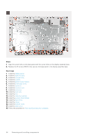
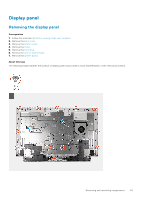
NOTE: The screws that secure the middle frame and display panel to the display-assembly base are silver in color and etched with "LCD" around the screw holes. 5. Remove the jig screw from the display panel. 6. Replace the screw (M3x5) that secure the display panel to the display-assembly base. Next steps 1. Install the system board. 2. Install the system-board shield. 3. Install the hard drive. 4. Install the stand. 5. Install the bottom cover. 6. Install the back cover. 7. Follow the procedure in After working inside your computer. Removing and installing components 59
-
 1
1 -
2
-
3
-
4
-
5
-
6
-
7
-
8
-
9
-
10
-
11
-
12
-
13
-
14
-
15
-
16
-
17
-
18
-
19
-
20
-
21
-
22
-
23
-
24
-
25
-
26
-
27
-
28
-
29
-
30
-
31
-
32
-
33
-
34
-
35
-
36
-
37
-
38
-
39
-
40
-
41
-
42
-
43
-
44
-
45
-
46
-
47
-
48
-
49
-
50
-
51
-
52
-
53
-
 54
54 -
 55
55 -
 56
56 -
 57
57 -
 58
58 -
 59
59 -
 60
60 -
 61
61 -
 62
62 -
 63
63 -
 64
64 -
65
-
66
-
67
-
68
-
69
-
70
-
71
-
72
-
73
 |
 |

NOTE:
The screws that secure the middle frame and display panel to the display-assembly base are silver in color and
etched with "LCD" around the screw holes.
5.
Remove the jig screw from the display panel.
6.
Replace the screw (M3x5) that secure the display panel to the display-assembly base.
Next steps
1.
Install the
system board
.
2.
Install the
system-board shield
.
3.
Install the
hard drive
.
4.
Install the
stand
.
5.
Install the
bottom cover
.
6.
Install the
back cover
.
7.
Follow the procedure in
After working inside your computer
.
Removing and installing components
59