Dell Latitude CPt V Service Manual - Page 27
Reinstall the seven 10-mm screws.
 |
View all Dell Latitude CPt V manuals
Add to My Manuals
Save this manual to your list of manuals |
Page 27 highlights
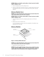
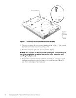
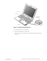
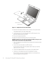
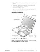
5. To push the keyboard down, press on the blank key located below the right key. 6. Check that the keyboard is correctly installed. The keys should be flush with the left and right surfaces of the palmrest. 7. Reinstall the seven 10-mm screws. Start by installing the outermost screws on the left and right sides of the computer and then work inward to the center. 3-mm screws (2) microprocessor shield captive screws (3) white marks on the microprocessor board (2) microprocessor module M2.0x3 thermal cooling assembly arm support.dell.com Dell Latitude CPt V-Series/CPx H-Series Service Manual 19
-
 1
1 -
2
-
3
-
4
-
5
-
6
-
7
-
8
-
9
-
10
-
11
-
12
-
13
-
14
-
15
-
16
-
17
-
18
-
19
-
20
-
21
-
 22
22 -
 23
23 -
 24
24 -
 25
25 -
 26
26 -
 27
27 -
 28
28 -
 29
29 -
 30
30 -
 31
31 -
 32
32 -
33
-
34
-
35
-
36
-
37
-
38
-
39
-
40
-
41
-
42
-
43
-
44
-
45
-
46
 |
 |

support.dell.com
Dell Latitude CPt V-Series/CPx H-Series Service Manual
19
5.
To push the keyboard down, press on the blank key located below the right
<Shift> key.
6.
Check that the keyboard is correctly installed. The keys should be flush
with the left and right surfaces of the palmrest.
7.
Reinstall the seven 10-mm screws.
Start by installing the outermost screws on the left and right sides of the
computer and then work inward to the center.
·ƳÃϳÃƼ¸¸Ã³ºÂôÄÀ¼
±²³´µ¶·¸Â¹··Ã²Îµ»½µ»Î¶ÇÇ»µ·Ã»!´É¶·Ê¶¼»ËÁÉ
±²³´µ¶·¸³Å¸¾Íź¼¸¼¾Ç¾Èº»È¸¿ÂÀ¸ÁËÁ¿ÀǸΞü"¸ËÅ̸ÇÌÁ¿¸ÃÀÇÅÍÀ¸¿ÂÀ¸
Ǿº»¸Î¾¿¿ÀÃ˸ÎÀÊÅÃÀ¸ËÅ̸ÁÀÃͺ½À¸¿ÂÀ¸½ÅÇÄÌ¿ÀÃÏ
3-mm screws (2)
microprocessor module
microprocessor shield
white marks on the
microprocessor board (2)
captive screws (3)
thermal cooling
assembly arm
M2.0x3