Dell Latitude CPt V Service Manual - Page 30
Lift the display assembly from the bottom case assembly., Pry the hinge cover loose at the seam
 |
View all Dell Latitude CPt V manuals
Add to My Manuals
Save this manual to your list of manuals |
Page 30 highlights
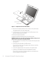
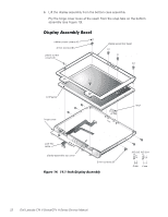
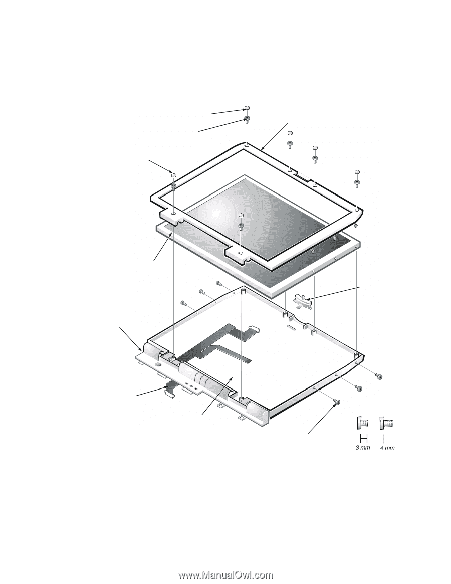
6. Lift the display assembly from the bottom case assembly. Pry the hinge cover loose at the seam from the snap tabs on the bottom assembly (see Figure 13). rubber screw covers (4) 4-mm screws (6) plastic screw covers (2) display assembly bezel LCD panel hinge cover latch LCD flex cable display-assembly top cover 3-mm screws (6) M2.0x3 M2.5x4 22 Dell Latitude CPt V-Series/CPx H-Series Service Manual
-
 1
1 -
2
-
3
-
4
-
5
-
6
-
7
-
8
-
9
-
10
-
11
-
12
-
13
-
14
-
15
-
16
-
17
-
18
-
19
-
20
-
21
-
22
-
23
-
24
-
 25
25 -
 26
26 -
 27
27 -
 28
28 -
 29
29 -
 30
30 -
 31
31 -
 32
32 -
 33
33 -
 34
34 -
 35
35 -
36
-
37
-
38
-
39
-
40
-
41
-
42
-
43
-
44
-
45
-
46
 |
 |
22
Dell Latitude CPt V-Series/CPx H-Series Service Manual
6.
Lift the display assembly from the bottom case assembly.
Pry the hinge cover loose at the seam from the snap tabs on the bottom
assembly (see Figure 13).
¶·¸ÏÀ²Áº½¸¸¼¾¿ÀÁºÅ¼'¼À
±
±²³´µ¶·¸(¹··¸(¹¸1°ÀÎ&·)²Ç½ÉÁÅ·ÆÇǶ¼ÈÉÅ
LCD panel
display-assembly top cover
LCD flex
cable
4-mm screws (6)
latch
rubber screw covers (4)
plastic screw
covers (2)
3-mm screws (6)
display assembly bezel
hinge cover
M2.0x3
M2.5x4