Dell Latitude CPt V Service Manual - Page 34
Attach the flex-cable clip to the bottom of the hinge cover located at
 |
View all Dell Latitude CPt V manuals
Add to My Manuals
Save this manual to your list of manuals |
Page 34 highlights
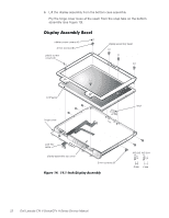
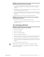
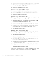
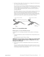
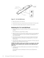
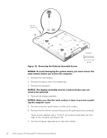
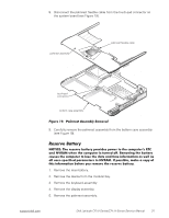
6. Disconnect the two-wire back-light plug from the connector on the inverter. 7. Lift the LCD panel and carefully disconnect the flex cable from the connector on the left edge of the LCD panel. 8. Remove the LCD panel from the top cover. 1. Disconnect the LCD flex cable from the ZIF connector on the inverter. 2. Remove the three 3-mm screws securing the inverter to the top cover. 3. Remove the inverter from the top cover. 1. Remove the 4-mm screw securing the metal cable clip to the left hinge of the display-assembly top cover (see Figure 15). 2. Remove the cable out from under the plastic strain relief retainer located on the bottom of the display-assembly hinge cover. 3. Remove the flex-cable clip from the bottom of the hinge cover located at the bottom of the display assembly. 4. Pry the hinge-cover assembly apart from the display assembly, allowing just enough space for the flex cable to pass through the opening. 5. Slide the cable through the opening. 1. Pry the hinge-cover assembly apart from the display assembly, allowing just enough space for the flex cable to pass through the opening. 2. Slide the cable through the opening. 3. Attach the flex-cable clip to the bottom of the hinge cover located at the bottom of the display assembly. 4. Slide the flex cable under the plastic strain relief retainer located on the bottom of the display-assembly hinge cover. 5. Reinstall the 4-mm screw that secures the metal cable clip to the left hinge of the display-assembly top cover. 6. Find the manufacturer's name on the back of the LCD panel that is to be installed. The manufacturer is either Torisan or Sharp. 26 Dell Latitude CPt V-Series/CPx H-Series Service Manual
-
 1
1 -
2
-
3
-
4
-
5
-
6
-
7
-
8
-
9
-
10
-
11
-
12
-
13
-
14
-
15
-
16
-
17
-
18
-
19
-
20
-
21
-
22
-
23
-
24
-
25
-
26
-
27
-
28
-
 29
29 -
 30
30 -
 31
31 -
 32
32 -
 33
33 -
 34
34 -
 35
35 -
 36
36 -
 37
37 -
 38
38 -
 39
39 -
40
-
41
-
42
-
43
-
44
-
45
-
46
 |
 |
