Dell Latitude CPt V Service Manual - Page 41
Snap in the new latch button from the bottom of the base, making certain
 |
View all Dell Latitude CPt V manuals
Add to My Manuals
Save this manual to your list of manuals |
Page 41 highlights
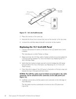
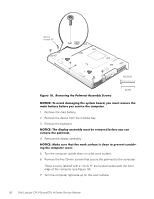
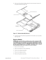
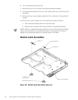
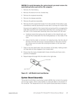
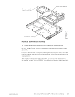
1. Remove the main battery. 2. Remove the device from the modular bay. 3. Remove the keyboard assembly. 4. Remove the display assembly. 5. Remove the palmrest assembly. 6. Remove the left module latch button from the outside of the bottom case assembly by carefully squeezing the snap tabs to unsnap the module latch. Keep pressure applied to the module latch and spring while unsnapping the snap tabs to prevent the module latch assembly from coming loose from the case. If the module latch assembly does come loose from the case: a. Carefully reinsert the spring onto the slider on the module latch, and reinstall the module latch into the holding features on the inside of the case. b. Ensure that the slider is inserted in its respective hole, that the side of the latch with the two bumps is facing the back of the case, and that the surface with the wear ribs is facing the bottom of the case (see Figure 21). 7. Snap in the new latch button from the bottom of the base, making certain its snap tabs are fully engaged in the module latch. 8. Ensure that the newly installed latch moves smoothly and freely when pushed and released. 9. Repeat steps 6 through 8 for the latch on the right side. bump side wear ribs (2) The system board's basic input/output system (BIOS) chip contains the system service tag number, which is also visible on a bar-code label on the bottom of the computer. The replacement kit for the system board assembly includes a support.dell.com Dell Latitude CPt V-Series/CPx H-Series Service Manual 33
-
 1
1 -
2
-
3
-
4
-
5
-
6
-
7
-
8
-
9
-
10
-
11
-
12
-
13
-
14
-
15
-
16
-
17
-
18
-
19
-
20
-
21
-
22
-
23
-
24
-
25
-
26
-
27
-
28
-
29
-
30
-
31
-
32
-
33
-
34
-
35
-
 36
36 -
 37
37 -
 38
38 -
 39
39 -
 40
40 -
 41
41 -
 42
42 -
 43
43 -
 44
44 -
 45
45 -
 46
46
 |
 |
