Dell Latitude E5500 Service Manual - Page 34
I/O Card - hard drive replacement
 |
View all Dell Latitude E5500 manuals
Add to My Manuals
Save this manual to your list of manuals |
Page 34 highlights
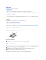
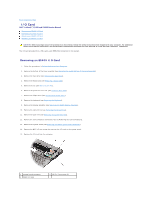
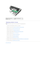
Back to Contents Page I/O Card Dell™ Latitude™ E5400 and E5500 Service Manual Removing an E5400 I/O Card Replacing an E5400 I/O Card Removing an E5500 I/O Card Replacing an E5500 I/O Card CAUTION: Before you begin any of the procedures in this section, follow the safety instructions that shipped with your computer. For additional safety best practices information, see the Regulatory Compliance Homepage on www.dell.com at: www.dell.com/regulatory_compliance. The I/O card provides DC-in, USB, audio, and IEEE 1394 connectors for the system. Removing an E5400 I/O Card 1. Follow the procedures in Before Working on Your Computer. 2. Remove the bottom of the base assembly (see Removing the E5400 Bottom of the Base Assembly). 3. Remove the hard drive (see Removing the Hard Drive). 4. Remove the WLAN card (see Removing a WLAN Card). 5. Remove the fan (see Removing the Fan). 6. Remove the processor heat sink (see Processor Heat Sink). 7. Remove the hinge cover (see Removing the Hinge Cover). 8. Remove the keyboard (see Removing the Keyboard). 9. Remove the display assembly (see Removing the E5400 Display Assembly). 10. Remove the optical drive (see Removing the Optical Drive). 11. Remove the palm rest (see Removing the E5400 Palm Rest). 12. Remove the coin cell battery connector (refer to Removing the Coin-Cell Battery). 13. Remove the system board (see Removing the E5400 System Board Assembly). 14. Remove the M2.5 x 5-mm screw that secures the I/O card to the system board. 15. Remove the I/O card from the computer. 1 system board connector 3 E5400 I/O card 2 M2.5 x 5-mm screw (1)
-
 1
1 -
2
-
3
-
4
-
5
-
6
-
7
-
8
-
9
-
10
-
11
-
12
-
13
-
14
-
15
-
16
-
17
-
18
-
19
-
20
-
21
-
22
-
23
-
24
-
25
-
26
-
27
-
28
-
 29
29 -
 30
30 -
 31
31 -
 32
32 -
 33
33 -
 34
34 -
 35
35 -
 36
36 -
 37
37 -
 38
38 -
 39
39 -
40
-
41
-
42
-
43
-
44
-
45
-
46
-
47
-
48
-
49
-
50
-
51
-
52
-
53
-
54
-
55
-
56
-
57
-
58
-
59
-
60
-
61
-
62
-
63
-
64
-
65
-
66
-
67
-
68
-
69
-
70
-
71
-
72
-
73
 |
 |