Dell Latitude E5500 Service Manual - Page 57
System Board Assembly
 |
View all Dell Latitude E5500 manuals
Add to My Manuals
Save this manual to your list of manuals |
Page 57 highlights
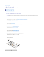
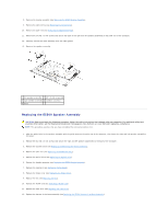
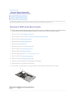
Back to Contents Page System Board Assembly Dell™ Latitude™ E5400 and E5500 Service Manual Removing the E5400 System Board Assembly Replacing the E5400 System Board Assembly Removing the E5500 System Board Assembly Replacing the E5500 System Board Assembly The system board's BIOS chip contains the Service Tag, which is also visible on a barcode label on the base of the computer. The replacement kit for the system board includes media that provide a utility for transferring the Service Tag to the replacement system board. Removing the E5400 System Board Assembly CAUTION: Before you begin the following procedure, follow the safety instructions that shipped with your computer. For additional safety best practices information, see the Regulatory Compliance Homepage on www.dell.com at: www.dell.com/regulatory_compliance. 1. Follow the instructions in Before Working on Your Computer. 2. Remove the bottom of the base assembly (see Removing the E5400 Bottom of the Base Assembly). 3. Remove the hard drive (see Removing the Hard Drive). 4. Remove the WLAN card (see Removing a WLAN Card). 5. Remove the fan (see Removing the Fan). 6. Remove the processor heat sink (see Processor Heat Sink). 7. Remove the hinge cover (see Removing the Hinge Cover). 8. Remove the keyboard (see Removing the Keyboard). 9. Remove the display assembly (see Removing the E5400 Display Assembly). 10. Remove the optical drive (see Removing the Optical Drive). 11. Remove the palm rest (see Removing the E5400 Palm Rest). 12. Remove the coin cell battery connector (refer to Removing the Coin-Cell Battery). 13. Remove the two M2.5 x 5-mm screws from the system board. 14. Lift the left edge of the system board off of the I/O board connector, and then carefully lift the system board out of the computer. 1 E5400 system board 2 M2.5 x 5-mm system board screws (2) 3 base
-
 1
1 -
2
-
3
-
4
-
5
-
6
-
7
-
8
-
9
-
10
-
11
-
12
-
13
-
14
-
15
-
16
-
17
-
18
-
19
-
20
-
21
-
22
-
23
-
24
-
25
-
26
-
27
-
28
-
29
-
30
-
31
-
32
-
33
-
34
-
35
-
36
-
37
-
38
-
39
-
40
-
41
-
42
-
43
-
44
-
45
-
46
-
47
-
48
-
49
-
50
-
51
-
 52
52 -
 53
53 -
 54
54 -
 55
55 -
 56
56 -
 57
57 -
 58
58 -
 59
59 -
 60
60 -
 61
61 -
 62
62 -
63
-
64
-
65
-
66
-
67
-
68
-
69
-
70
-
71
-
72
-
73
 |
 |
