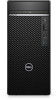
Dell OptiPlex 7071 Tower Tower Service Manual
Dell OptiPlex 7071 Tower Manual
 |
View all Dell OptiPlex 7071 Tower manuals
Add to My Manuals
Save this manual to your list of manuals |
Dell OptiPlex 7071 Tower manual content summary:
- Dell OptiPlex 7071 Tower | Tower Service Manual - Page 1
OptiPlex 7071 Tower Service Manual Regulatory Model: D28M Regulatory Type: D28M001 - Dell OptiPlex 7071 Tower | Tower Service Manual - Page 2
and tells you how to avoid the problem. WARNING: A WARNING indicates a potential for property damage, personal injury, or death. © 2019 - 2020 Dell Inc. or its subsidiaries. All rights reserved. Dell, EMC, and other trademarks are trademarks of Dell Inc. or its subsidiaries. Other trademarks may - Dell OptiPlex 7071 Tower | Tower Service Manual - Page 3
Contents 1 Working on your computer...6 Safety instructions...6 Before working inside your computer...6 Safety precautions...7 Electrostatic discharge-ESD protection...7 ESD field service kit ...8 Transporting sensitive components...9 After working inside your computer...9 2 Major components of - Dell OptiPlex 7071 Tower | Tower Service Manual - Page 4
58 Installing the intrusion switch...59 System board...60 Removing the system board...60 Installing the system board...64 4 System setup...69 Entering BIOS setup program...69 Boot menu...69 Navigation keys...69 Boot Sequence...70 System setup options...70 General options...70 System information...71 - Dell OptiPlex 7071 Tower | Tower Service Manual - Page 5
management...76 Post behavior...76 Manageability...77 Virtualization support...77 Wireless options...78 Maintenance...78 System logs... BIOS using a USB flash drive 81 Updating the Dell BIOS in Linux and Ubuntu environments 82 Flashing the BIOS from the F12 One-Time boot menu 82 5 Troubleshooting - Dell OptiPlex 7071 Tower | Tower Service Manual - Page 6
only perform troubleshooting and simple repairs as authorized in your product documentation, or as directed by the online or telephone service and support team. Damage due to servicing that is not authorized by Dell is not covered by your warranty. Read and follow the safety instructions that came - Dell OptiPlex 7071 Tower | Tower Service Manual - Page 7
disassembly instructions. Observe getting electrocuted. Standby power Dell products with standby power done through the use of a field service electrostatic discharge (ESD) kit. When obvious, such as intermittent problems or a shortened product life troubleshoot is the intermittent (also called - Dell OptiPlex 7071 Tower | Tower Service Manual - Page 8
is different than for a desktop or portable environment. Servers are typically installed in a rack within a data center; desktops or portables are typically service technicians use the traditional wired ESD grounding wrist strap and protective anti-static mat at all times when servicing Dell - Dell OptiPlex 7071 Tower | Tower Service Manual - Page 9
such as replacement parts or parts to be returned to Dell, it is critical to place these parts in anti-static apart for a stable base, and point your toes out. 2. Tighten stomach muscles. Abdominal muscles support your spine when you lift, offsetting the force of the load. 3. Lift with your legs, - Dell OptiPlex 7071 Tower | Tower Service Manual - Page 10
2 Major components of your system 1. Left-side cover 2. 3.5-inch hard drive 3. Slim optical-drive 4. Processor fan and heat-sink assembly 5. Processor 6. Memory module 7. Solid-state drive/Intel Optane 8. Power button 9. System board 10. Front I/O port bracket 11. Front cover 12. Chassis 13. - Dell OptiPlex 7071 Tower | Tower Service Manual - Page 11
NOTE: Dell provides a list of components and their part numbers for the original system configuration purchased. These parts are available according to warranty coverages purchased by the customer. Contact your Dell sales representative for purchase options. Major components of your system 11 - Dell OptiPlex 7071 Tower | Tower Service Manual - Page 12
3 Disassembly and reassembly Recommended tools The procedures in this document require the following tools: • Phillips #0 screwdriver • Phillips #1 screwdriver • Philips #2 screwdriver • Plastic scribe • Hex screwdriver Screw list NOTE: When removing screws from a component, it is recommended to - Dell OptiPlex 7071 Tower | Tower Service Manual - Page 13
Left-side cover Removing the left-side cover Prerequisites 1. Follow the procedure in Before working inside your computer. About this task The following images indicate the location of the left-side cover and provides a visual representation of the removal procedure. Disassembly and reassembly 13 - Dell OptiPlex 7071 Tower | Tower Service Manual - Page 14
Steps 1. Push the release latch down to unlock the side cover. 2. Using the tab on the left-side cover, slide and lift the left-side cover off the chassis. Installing the left-side cover Prerequisites If you are replacing a component, remove the existing component before performing the installation - Dell OptiPlex 7071 Tower | Tower Service Manual - Page 15
Steps 1. Align the tabs on the left-side cover with the slots on the chassis. 2. Slide it towards the front of the computer until the release latch locks the side cover. Next steps 1. Follow the procedure in After working inside your computer. Disassembly and reassembly 15 - Dell OptiPlex 7071 Tower | Tower Service Manual - Page 16
Front cover Removing the front cover Prerequisites 1. Follow the procedure in Before working inside your computer. 2. Remove the left-side cover. About this task The following images indicate the location of the front cover and provide a visual representation of the removal procedure. Steps 1. - Dell OptiPlex 7071 Tower | Tower Service Manual - Page 17
About this task The following images indicate the location of the front cover and provide a visual representation of the installation procedure. Steps 1. Place the computer in an upright position. 2. Align the front-cover tabs with the slots on the chassis. 3. Move the front cover towards the - Dell OptiPlex 7071 Tower | Tower Service Manual - Page 18
About this task The following images indicate the location of the 2.5-inch hard drive assembly and provides a visual representation of the removal procedure. Steps 1. Disconnect the data and power cables from the hard drive. 2. Press the release tabs on the hard-drive bracket and slide the hard- - Dell OptiPlex 7071 Tower | Tower Service Manual - Page 19
Steps 1. NOTE: Note the orientation or the SATA connector marking on the hard drive so that you can replace it correctly. Slide the hard-drive assembly into the hard-drive cage until it snaps into place. 2. Connect the data cable and power cable to the hard drive. Next steps 1. Install the left- - Dell OptiPlex 7071 Tower | Tower Service Manual - Page 20
3. Remove the 2.5-inch hard drive assembly. About this task The following images indicate the location of the 2.5-inch hard drive bracket and provides a visual representation of the removal procedure. Steps 1. Pry the hard-drive bracket to release the tabs on the assembly from the slots on the hard - Dell OptiPlex 7071 Tower | Tower Service Manual - Page 21
Steps 1. Place the hard drive into the hard-drive bracket and align the tabs on the bracket with the slots on the hard drive. 2. Snap the hard drive into the hard-drive bracket. Next steps 1. Install the 2.5-inch hard drive assembly. 2. Install the left-side cover. 3. Follow the procedure in After - Dell OptiPlex 7071 Tower | Tower Service Manual - Page 22
Steps 1. Lay the computer on the right side. 2. Disconnect the data and power cables from the hard drive. 3. Push the securing tab to release the hard drive bracket from the chassis. 4. Remove the EMI shied from the front-side of the chassis. 5. Slide the hard-drive assembly away from the chassis. - Dell OptiPlex 7071 Tower | Tower Service Manual - Page 23
shield on the chassis. 3. Align the hard-drive assembly with the tabs on the chassis. 4. Route the power cable and data cable through the routing guides on the hard-drive assembly and connect the cables to the hard drive. Next steps 1. Install the left-side cover. 2. Follow the procedure in After - Dell OptiPlex 7071 Tower | Tower Service Manual - Page 24
3.5-inch hard drive bracket Removing the 3.5-inch hard drive bracket Prerequisites 1. Follow the procedure in Before working inside your computer. 2. Remove the left-side cover. 3. Remove the 3.5-inch hard drive assembly. About this task The following images indicate the location of the 3.5-inch - Dell OptiPlex 7071 Tower | Tower Service Manual - Page 25
About this task The following images indicate the location of the 3.5-inch hard drive bracket and provides a visual representation of the installation procedure. Steps 1. Place the hard drive into the hard-drive bracket and align the tabs on the bracket with the slots on the hard drive. 2. Snap the - Dell OptiPlex 7071 Tower | Tower Service Manual - Page 26
Steps 1. Lay the computer on the right side. 2. Disconnect the data and power cables from the ODD. 3. Push the securing tab to release the ODD from the chassis. 4. Slide and remove the ODD from the ODD slot. Installing the Optical Disk Drive Prerequisites If you are replacing a component, remove the - Dell OptiPlex 7071 Tower | Tower Service Manual - Page 27
ODD assembly into the ODD slot. 2. Slide the ODD assembly until it snaps into place. 3. Route the power cable and data cable through the routing guides and connect the cables to the ODD. Next steps 1. Install the left-side cover. 2. Follow the procedure in After working inside your computer. Slim - Dell OptiPlex 7071 Tower | Tower Service Manual - Page 28
3. Remove the slim ODD assembly. About this task The following images indicate the location of the slim ODD bracket and provides a visual representation of the removal procedure. Steps 1. Pry the ODD bracket to release from the slots on the ODD. 2. Remove the ODD bracket off the ODD Installing the - Dell OptiPlex 7071 Tower | Tower Service Manual - Page 29
Next steps 1. Install the slim ODD assembly. 2. Install the left-side cover. 3. Follow the procedure in After working inside your computer. Chassis fan Removing the chassis fan Prerequisites 1. Follow the procedure in Before working inside your computer. 2. Remove the left-side cover. About this - Dell OptiPlex 7071 Tower | Tower Service Manual - Page 30
2. Disconnect the fan cable from the system board. 3. Gently pull the rubber grommets to release the fan from the chassis . 4. Remove the fan off the chassis. Installing the chassis fan Prerequisites If you are replacing a component, remove the existing component before performing the installation - Dell OptiPlex 7071 Tower | Tower Service Manual - Page 31
Next steps 1. Install the left-side cover. 2. Follow the procedure in After working inside your computer. Memory modules Removing the memory modules Prerequisites 1. Follow the procedure in Before working inside your computer. 2. Remove the left-side cover. About this task The following images - Dell OptiPlex 7071 Tower | Tower Service Manual - Page 32
CAUTION: To prevent damage to the memory module, hold the memory module by the edges. Do not touch the components on the memory module. Installing the memory modules Prerequisites If you are replacing a component, remove the existing component before performing the installation procedure. About this - Dell OptiPlex 7071 Tower | Tower Service Manual - Page 33
Wireless card Removing the wireless card Prerequisites 1. Follow the procedure in Before working inside your computer. 2. Remove the left-side cover. About this task The following images indicate the location of the wireless card and provides a visual representation of the removal procedure. Steps - Dell OptiPlex 7071 Tower | Tower Service Manual - Page 34
-card slot. 3. Connect the antenna cables to the wireless card. The following table provides the antenna-cable color scheme for the wireless card supported by your computer. Table 2. Antenna-cable color scheme Connectors on the wireless card Main (white triangle) Antenna-cable color White 34 - Dell OptiPlex 7071 Tower | Tower Service Manual - Page 35
Connectors on the wireless card Antenna-cable color Auxiliary (black triangle) Black 4. Slide and place the wireless-card bracket on the wireless card. 5. Replace the single (M2x3) screw that secures the wireless card to the system board. Next steps 1. Install the left-side cover. 2. Follow the - Dell OptiPlex 7071 Tower | Tower Service Manual - Page 36
Installing the 2230 solid-state drive/Intel Optane memory module Prerequisites CAUTION: Solid-state drives are fragile. Exercise care when handling the solid-state drive. If you are replacing a component, remove the existing component before performing the installation procedure. About this task The - Dell OptiPlex 7071 Tower | Tower Service Manual - Page 37
Removing the 2280 solid-state drive/Intel Optane memory module Prerequisites NOTE: You need to disable the Intel Optane memory before removing Intel Optane memory module from your computer. For more information about disabling the Intel Optane memory, see Disabling Intel Optane memory. 1. Follow the - Dell OptiPlex 7071 Tower | Tower Service Manual - Page 38
Steps 1. Locate the notch on the 2230 solid-state drive/Intel Optane memory. 2. Align the notch on the 2230 solid-state drive/Intel Optane memory with the tab on the M.2 card slot. 3. Slide the 2230 solid-state drive/Intel Optane memory into the M.2 card slot on the system board. 4. Replace the - Dell OptiPlex 7071 Tower | Tower Service Manual - Page 39
Steps 1. Lay the computer on the right side. 2. Locate the graphics card (PCI-Express). 3. Lift the pull tab to open the PCIe door. 4. Push and hold the securing tab on the graphics-card slot and lift the graphics card from the graphics-card slot. NOTE: To remove the NVIDIA GeForce RTX 2080 graphics - Dell OptiPlex 7071 Tower | Tower Service Manual - Page 40
Steps 1. Align the graphics card with the PCI-Express card connector on the system board. NOTE: To install the NVIDIA GeForce RTX 2080 graphics card, rotate and install the graphics card. 2. Using the alignment post, connect the card in the connector and press down firmly. Ensure that the card is - Dell OptiPlex 7071 Tower | Tower Service Manual - Page 41
setup program's settings to default. It is recommended that you note the BIOS setup program's settings before removing the coin-cell battery. 2. Remove the left-side cover. 3. Remove the multiple graphics cards. About this task The following images - Dell OptiPlex 7071 Tower | Tower Service Manual - Page 42
Insert the coin-cell battery into the socket with the positive side (+) labeled facing up and snap the battery in the socket. Next steps 1. Install the multiple graphics cards. 2. Install the left-side cover. 3. Follow the procedure in After working inside your computer. Power-supply unit Removing - Dell OptiPlex 7071 Tower | Tower Service Manual - Page 43
Disassembly and reassembly 43 - Dell OptiPlex 7071 Tower | Tower Service Manual - Page 44
Steps 1. Lay the computer on the right side. 2. Disconnect the power cables from the system board and remove them from the routing guides on the chassis. 3. Remove the three (#6-32) screws that secure the power-supply unit to the chassis. 4. Press the securing clip and slide the power- - Dell OptiPlex 7071 Tower | Tower Service Manual - Page 45
Disassembly and reassembly 45 - Dell OptiPlex 7071 Tower | Tower Service Manual - Page 46
into position. 2. Replace the three screws (#6-32) that secure the power-supply unit to the chassis. 3. Route the power cable through the routing guides on the chassis and connect the power cables to their respective connectors on the system board. Next steps 1. Install the processor fan and heat - Dell OptiPlex 7071 Tower | Tower Service Manual - Page 47
Processor fan and heat-sink assembly Removing the processor fan and 95 W heat-sink assembly Prerequisites 1. Follow the procedure in Before working inside your computer. WARNING: The heat sink may become hot during normal operation. Allow sufficient time for the heat sink to cool before you touch it - Dell OptiPlex 7071 Tower | Tower Service Manual - Page 48
Installing the processor fan and 95 W heat-sink assembly Prerequisites If you are replacing a component, remove the existing component before performing the installation procedure. CAUTION: If either the processor or the heat sink is replaced, use the thermal grease provided in the kit to ensure - Dell OptiPlex 7071 Tower | Tower Service Manual - Page 49
Removing the processor fan and 65 W heat-sink assembly Prerequisites 1. Follow the procedure in Before working inside your computer. WARNING: The heat sink may become hot during normal operation. Allow sufficient time for the heat sink to cool before you touch it. CAUTION: For maximum cooling of the - Dell OptiPlex 7071 Tower | Tower Service Manual - Page 50
CAUTION: If either the processor or the heat sink is replaced, use the thermal grease provided in the kit to ensure that thermal conductivity is achieved. About this task The following images indicate the location of the processor fan and 65 W heat-sink assembly and provides a visual representation - Dell OptiPlex 7071 Tower | Tower Service Manual - Page 51
NOTE: The processor might still be hot after the computer is shut down. Allow the processor to cool down before removing it. About this task The following images indicate the location of the processor and provides a visual representation of the removal procedure. Steps 1. Press the release lever - Dell OptiPlex 7071 Tower | Tower Service Manual - Page 52
About this task The following images indicate the location of the processor and provides a visual representation of the installation procedure. Steps 1. Ensure that the release lever on the processor socket is fully extended in the open position. NOTE: The pin-1 corner of the processor has a - Dell OptiPlex 7071 Tower | Tower Service Manual - Page 53
VR heat sink Removing the VR heat sink Prerequisites 1. Follow the procedure in Before working inside your computer. WARNING: The heat sink may become hot during normal operation. Allow sufficient time for the heat sink to cool before you touch it. CAUTION: For maximum cooling of the processor, do - Dell OptiPlex 7071 Tower | Tower Service Manual - Page 54
Steps 1. Align and place the VR heat sink on the system board. 2. Tighten the two captive screws that secure the VR heat sink to the system board. Next steps 1. Install the left-side cover. 2. Follow the procedure in After working inside your computer. Speaker Removing the speaker Prerequisites 1. - Dell OptiPlex 7071 Tower | Tower Service Manual - Page 55
Steps 1. Lay the computer on the right side. 2. Disconnect the speaker cable from the system board. 3. Press and slide the speaker to remove from the slots on the chassis . Installing the speaker Prerequisites If you are replacing a component, remove the existing component before performing the - Dell OptiPlex 7071 Tower | Tower Service Manual - Page 56
Steps 1. Press and slide the speaker in the slot on the chassis until it snaps into place. 2. Connect the speaker cable to the system board. Next steps 1. Install the left-side cover. 2. Follow the procedure in After working inside your computer. Power button Removing the power button Prerequisites - Dell OptiPlex 7071 Tower | Tower Service Manual - Page 57
Steps 1. Lay the computer on the right side. 2. Disconnect the power button cable from the system board. 3. Press the release tabs and slide the power button out from the front-side of the computer. 4. Pull the power button out from the computer. Installing the power button Prerequisites If you are - Dell OptiPlex 7071 Tower | Tower Service Manual - Page 58
Steps 1. Insert the power button switch into the slot from the front-side of the computer, and press until it clicks into the place. 2. Align and connect the power button cable to the system board. Next steps 1. Install the left-side cover. 2. Follow the procedure in After working inside your - Dell OptiPlex 7071 Tower | Tower Service Manual - Page 59
Steps 1. Lay the computer on the right side. 2. Disconnect the intruder cable from the system board. 3. Slide and remove the intrusion switch from the chassis. Installing the intrusion switch Prerequisites If you are replacing a component, remove the existing component before performing the - Dell OptiPlex 7071 Tower | Tower Service Manual - Page 60
the system board Prerequisites 1. Follow the procedure in Before working inside your computer. NOTE: Your computer's Service Tag is stored in the system board. You must enter the Service Tag in the BIOS setup program after you replace the system board. NOTE: Replacing the system board removes any - Dell OptiPlex 7071 Tower | Tower Service Manual - Page 61
10. Remove the VR heat sink. 11. Remove the processor. About this task The following images indicate the location of the system board and provides a visual representation of the removal procedure. Disassembly and reassembly 61 - Dell OptiPlex 7071 Tower | Tower Service Manual - Page 62
62 Disassembly and reassembly - Dell OptiPlex 7071 Tower | Tower Service Manual - Page 63
Disassembly and reassembly 63 - Dell OptiPlex 7071 Tower | Tower Service Manual - Page 64
Steps 1. Lay the computer on the right side. 2. Remove the screw (#6-32) that secures the front I/O-bracket to the chassis. 3. Slide and remove the front I/O-bracket from the chassis. 4. Disconnect all the cables that are connected to the system board. 5. Remove the eight (#6-32) screws that secure - Dell OptiPlex 7071 Tower | Tower Service Manual - Page 65
Disassembly and reassembly 65 - Dell OptiPlex 7071 Tower | Tower Service Manual - Page 66
66 Disassembly and reassembly - Dell OptiPlex 7071 Tower | Tower Service Manual - Page 67
Disassembly and reassembly 67 - Dell OptiPlex 7071 Tower | Tower Service Manual - Page 68
the left-side cover. 11. Follow the procedure in After working inside your computer. NOTE: Your computer's Service Tag is stored in the system board. You must enter the Service Tag in the BIOS setup program after you replace the system board. NOTE: Replacing the system board removes any changes that - Dell OptiPlex 7071 Tower | Tower Service Manual - Page 69
on (or restart) your computer and press F2 immediately. Boot menu Press when the Dell logo appears to initiate a one-time boot menu with a list of the valid boot devices for the system. Diagnostics and BIOS Setup options are also included in this menu. The devices listed on the boot menu - Dell OptiPlex 7071 Tower | Tower Service Manual - Page 70
example: optical drive or hard drive). During the Power-on Self-Test (POST), when the Dell logo appears, you can: • Access System Setup by pressing F2 key • Bring up the : Displays BIOS Version, Service Tag, Asset Tag, Ownership Tag, Manufacture Date, Ownership Date, and Express Service Code. - Dell OptiPlex 7071 Tower | Tower Service Manual - Page 71
controller. The options are: • Disabled-The SATA controllers are hidden • AHCI-SATA is configured for AHCI mode • RAID ON-SATA is configured to support RAID mode. This option is enabled by default. Drives Allows you to enable or disable various drives on-board: • SATA-0 • SATA-1 • SATA-2 • SATA - Dell OptiPlex 7071 Tower | Tower Service Manual - Page 72
disable the integrated USB controller. The options are: • Enable USB Boot Support-enabled by default • Enable Front USB Ports-enabled by default • Enable to enable or disable BIOS messages for maintaining the optional dust filter that is installed on your computer. BIOS generates a preboot reminder - Dell OptiPlex 7071 Tower | Tower Service Manual - Page 73
through UEFI capsule update packages. This option is enabled by default. Disabling this option blocks BIOS updates from services such as Microsoft Windows Update and Linux Vendor Firmware Service (LVFS) Allows you to control whether the Trusted Platform Module (TPM) is visible to the operating - Dell OptiPlex 7071 Tower | Tower Service Manual - Page 74
disabled by default. When enabled, this option disables master password support. This option is disabled by default. Allows you to enable modify the behavior of Secure Boot to allow evaluation or enforcement of UEFI driver signatures. • Deployed Mode (default) • Audit Mode Allows you to manipulate - Dell OptiPlex 7071 Tower | Tower Service Manual - Page 75
Reserve Memory size. The options are: • 32 MB • 64 MB • 128 MB-enabled by default Performance Table 9. Performance Option Multi Core Support Intel SpeedStep C-States Control Intel TurboBoost Hyper-Thread Control Description This field specifies whether the process has one or all cores enabled. The - Dell OptiPlex 7071 Tower | Tower Service Manual - Page 76
USB devices to wake the computer from standby mode. The option "Enable USB Wake Support" is selected by default This option enables the computer to power up from the off Minimal - The system boots quickly, unless the BIOS has been updated, memory changed, or the previous POST did not complete. 76 - Dell OptiPlex 7071 Tower | Tower Service Manual - Page 77
Option Extend BIOS POST Time Full Screen Logo Warnings and Errors Description • Thorough - The system does not skip any steps in the boot process. • Auto - This allows the operating system to control this setting (this works only when the operating system supports Simple Boot Flag). This option is - Dell OptiPlex 7071 Tower | Tower Service Manual - Page 78
/WiGig • Bluetooth All the options are enabled by default. Maintenance Table 15. Maintenance Option Service Tag Asset Tag SERR Messages BIOS Downgrade Data Wipe Bios Recovery First Power On Date Description Displays the service tag of your computer. If an asset tag is not set, this option enables - Dell OptiPlex 7071 Tower | Tower Service Manual - Page 79
status is in Not Set. About this task To enter the system setup, press F2 immediately after a power-on or reboot. Steps 1. In the System BIOS or System Setup screen, select Security and press Enter. The Security screen is displayed. 2. Select System/Admin Password and create a password in the Enter - Dell OptiPlex 7071 Tower | Tower Service Manual - Page 80
the changes and exit from System Setup. The computer restarts. Clearing CMOS settings About this task CAUTION: Clearing CMOS settings will reset the BIOS settings on your computer. Steps 1. Remove the left-side cover. 2. Remove the graphics card. 3. Remove the jumper plug from the password jumper - Dell OptiPlex 7071 Tower | Tower Service Manual - Page 81
suspended prior to updating the system BIOS, and then re enabled after the BIOS update is completed. Steps 1. Restart the computer. 2. Go to Dell.com/support. • Enter the Service Tag or Express Service Code and click Submit. • Click Detect Product and follow the instructions on screen. 3. If you are - Dell OptiPlex 7071 Tower | Tower Service Manual - Page 82
One-Time boot menu, you will need: • USB key formatted to the FAT32 file system (key does not have to be bootable) • BIOS executable file that you downloaded from the Dell Support website and copied to the root of the USB key • AC power adapter connected to the system • Functional system battery to - Dell OptiPlex 7071 Tower | Tower Service Manual - Page 83
3. The Bios Flash Update dialog box menu is opened. Click BIOS Update file browse button to select the BIOS file. System setup 83 - Dell OptiPlex 7071 Tower | Tower Service Manual - Page 84
4. Select the BIOS executable file and then press OK. Switch to correct catalogue of your external USB device by File system if you do not find the BIOS executable file. 84 System setup - Dell OptiPlex 7071 Tower | Tower Service Manual - Page 85
5. Click Begin Flash Update, and then a warning message is displayed. System setup 85 - Dell OptiPlex 7071 Tower | Tower Service Manual - Page 86
6. Click Yes. The systems restarts automatically and starts BIOS Flash. 86 System setup - Dell OptiPlex 7071 Tower | Tower Service Manual - Page 87
7. Once complete, the system will reboot and the BIOS update process is completed. System setup 87 - Dell OptiPlex 7071 Tower | Tower Service Manual - Page 88
Troubleshooting Enhanced Pre-Boot System Assessment (ePSA) diagnostics About this task The ePSA diagnostics (also known as system diagnostics) performs a complete check of your hardware. The ePSA is embedded with the BIOS and is launched by the BIOS problems number and contact Dell. Diagnostics The - Dell OptiPlex 7071 Tower | Tower Service Manual - Page 89
coin cell - Row M of table 12.4 in SIO spec [40] System state BIOS state 1 BIOS state 2 BIOS state 3 Notes BIOS Post code (Old LED pattern 0001) Corrupt BIOS. BIOS Post code (Old LED pattern 0010) CPU config or CPU failure. BIOS Post code (Old LED pattern 0011) MEM config in Troubleshooting 89 - Dell OptiPlex 7071 Tower | Tower Service Manual - Page 90
or failure. BIOS to eliminate 0111 USB code. BIOS Post code (Old LED pattern 1000) MEM config, no memory detected. BIOS Post code (Old LED pattern 1001) Fatal Motherboard error. BIOS Post code (Old hard drive failed initialization. Run the hard drive tests in Dell Diagnostics. 90 Troubleshooting - Dell OptiPlex 7071 Tower | Tower Service Manual - Page 91
, and restart the computer. If the problem persists, try another drive. Run the Hard Disk Drive tests in Dell Diagnostics. The hard drive does not respond Dell Diagnostics. For external keyboards, check the cable connection. Run the Keyboard Controller test in Dell Diagnostics. Troubleshooting - Dell OptiPlex 7071 Tower | Tower Service Manual - Page 92
Help and Support for instructions (click Start > Help and Support). If a Dell. The reserve battery that supports the system configuration settings may require recharging. Connect your computer to an electrical outlet to charge the battery. If the problem persists, Contact Dell. 92 Troubleshooting - Dell OptiPlex 7071 Tower | Tower Service Manual - Page 93
error. resolving this problem, please note this checkpoint and contact Dell Technical Support CMOS checksum error RTC is reset, BIOS Setup default has been its factory state. You can also download it from the Dell Support website to troubleshoot and fix your computer when it fails to boot into - Dell OptiPlex 7071 Tower | Tower Service Manual - Page 94
Dell SupportAssist OS Recovery, see Dell SupportAssist OS Recovery User's Guide at www.dell.com/ support Optane memory, do not uninstall the driver for Intel Rapid Storage Technology as been removed. The following procedure provides the instructions on how to conduct flea power release: Troubleshooting - Dell OptiPlex 7071 Tower | Tower Service Manual - Page 95
to WiFi connectivity issues a WiFi power cycle procedure may be performed. The following procedure provides the instructions on how to conduct a WiFi power cycle: NOTE: Some ISPs (Internet Service Providers) provide a modem/router combo device. Steps 1. Turn off your computer. 2. Turn off the modem - Dell OptiPlex 7071 Tower | Tower Service Manual - Page 96
. Availability varies by country and product, and some services may not be available in your area. To contact Dell for sales, technical support, or customer service issues: Steps 1. Go to Dell.com/support. 2. Select your support category. 3. Verify your country or region in the Choose a Country
-
 1
1 -
 2
2 -
 3
3 -
 4
4 -
 5
5 -
 6
6 -
 7
7 -
8
-
9
-
10
-
11
-
12
-
13
-
14
-
15
-
16
-
17
-
18
-
19
-
20
-
21
-
22
-
23
-
24
-
25
-
26
-
27
-
28
-
29
-
30
-
31
-
32
-
33
-
34
-
35
-
36
-
37
-
38
-
39
-
40
-
41
-
42
-
43
-
44
-
45
-
46
-
47
-
48
-
49
-
50
-
51
-
52
-
53
-
54
-
55
-
56
-
57
-
58
-
59
-
60
-
61
-
62
-
63
-
64
-
65
-
66
-
67
-
68
-
69
-
70
-
71
-
72
-
73
-
74
-
75
-
76
-
77
-
78
-
79
-
80
-
81
-
82
-
83
-
84
-
85
-
86
-
87
-
88
-
89
-
90
-
91
-
92
-
93
-
94
-
95
-
96
 |
 |

OptiPlex 7071 Tower
Service Manual
Regulatory Model: D28M
Regulatory Type: D28M001