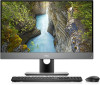
Dell OptiPlex 7770 All In One OptiPlex 7770 All-in-One Service Manual - Page 13
Removing and Installing components, Recommended tools
 |
View all Dell OptiPlex 7770 All In One manuals
Add to My Manuals
Save this manual to your list of manuals |
Page 13 highlights
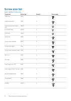
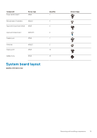
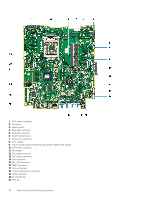
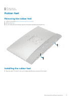
3 Removing and Installing components Topics: • Recommended tools • Screw size list • System board layout • Rubber feet • Cable cover - optional • Stand • Back cover • Hard drive • Solid State Drive -SSD • Solid State Drive -2230 • Memory module • System board shield • Intel Optane • WLAN card • System fan • Heat sink • Pop-Up Camera • Coin cell battery • Processor • Base cover • Power supply unit - PSU • Power supply unit fan - PSU fan • Input and Output bracket • System board • Speakers • Power button board • Microphones • Input and Output board • Headset port • Antennas • Display panel • Display cable • Middle frame Recommended tools The procedures in this document require the following tools: • Phillips #0 screwdriver • Phillips #1 screwdriver • Plastic scribe NOTE: The #0 screw driver is for screws 0-1 and the #1 screw driver is for screws 2-4 Removing and Installing components 13
-
 1
1 -
2
-
3
-
4
-
5
-
6
-
7
-
 8
8 -
 9
9 -
 10
10 -
 11
11 -
 12
12 -
 13
13 -
 14
14 -
 15
15 -
 16
16 -
 17
17 -
 18
18 -
19
-
20
-
21
-
22
-
23
-
24
-
25
-
26
-
27
-
28
-
29
-
30
-
31
-
32
-
33
-
34
-
35
-
36
-
37
-
38
-
39
-
40
-
41
-
42
-
43
-
44
-
45
-
46
-
47
-
48
-
49
-
50
-
51
-
52
-
53
-
54
-
55
-
56
-
57
-
58
-
59
-
60
-
61
-
62
-
63
-
64
-
65
-
66
-
67
-
68
-
69
-
70
-
71
-
72
-
73
-
74
-
75
-
76
-
77
-
78
-
79
-
80
-
81
-
82
-
83
-
84
-
85
-
86
-
87
-
88
-
89
-
90
-
91
-
92
-
93
-
94
-
95
-
96
 |
 |
