Dell OptiPlex GXa Service Manual - Page 141
System Board
 |
View all Dell OptiPlex GXa manuals
Add to My Manuals
Save this manual to your list of manuals |
Page 141 highlights
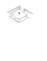
System Board screw slots (5) tabs (5) Figure 6-19. System Board Removal To remove the system board, follow these steps: 1. Disconnect all cables from their connectors at the back of the computer. 2. Remove the expansion-card cage. 3. Disconnect all cables from the system board. 4. Remove the screw that secures the system board to the bottom of the chassis. 5. Slide the system board toward the front of the chassis until it stops. 6. Carefully lift the system board out of the chassis (be sure to lift evenly and not twist the system board). NOTES: If you are replacing the system board, remove all DIMMs, the videomemory upgrade module (if present), the single-edge contact (SEC) cartridge/ heat sink assembly, and the guide bracket assembly from the old system board and install them on the replacement board. Also, set the jumpers on the new system board so they are identical to those on the old board, unless a microprocessor upgrade is being installed. If the original system board is an EM system board type, replace with an EM system board type. Also, if the original system board is equipped with a NIC connector, ensure that the replacement board contains a NIC connector. When you reinstall the system board (before you slide the system board back to lock it in position), push down near each slot to engage the grounding clip onto its corresponding tab. Push evenly on both sides of the system board as you slide it into position (do not twist the system board). Removing and Replacing Parts on the Mini Tower Chassis 6-21
-
 1
1 -
2
-
3
-
4
-
5
-
6
-
7
-
8
-
9
-
10
-
11
-
12
-
13
-
14
-
15
-
16
-
17
-
18
-
19
-
20
-
21
-
22
-
23
-
24
-
25
-
26
-
27
-
28
-
29
-
30
-
31
-
32
-
33
-
34
-
35
-
36
-
37
-
38
-
39
-
40
-
41
-
42
-
43
-
44
-
45
-
46
-
47
-
48
-
49
-
50
-
51
-
52
-
53
-
54
-
55
-
56
-
57
-
58
-
59
-
60
-
61
-
62
-
63
-
64
-
65
-
66
-
67
-
68
-
69
-
70
-
71
-
72
-
73
-
74
-
75
-
76
-
77
-
78
-
79
-
80
-
81
-
82
-
83
-
84
-
85
-
86
-
87
-
88
-
89
-
90
-
91
-
92
-
93
-
94
-
95
-
96
-
97
-
98
-
99
-
100
-
101
-
102
-
103
-
104
-
105
-
106
-
107
-
108
-
109
-
110
-
111
-
112
-
113
-
114
-
115
-
116
-
117
-
118
-
119
-
120
-
121
-
122
-
123
-
124
-
125
-
126
-
127
-
128
-
129
-
130
-
131
-
132
-
133
-
134
-
135
-
 136
136 -
 137
137 -
 138
138 -
 139
139 -
 140
140 -
 141
141 -
 142
142 -
 143
143 -
 144
144 -
 145
145 -
 146
146 -
147
-
148
-
149
-
150
-
151
-
152
-
153
-
154
-
155
-
156
-
157
-
158
-
159
-
160
-
161
-
162
-
163
-
164
-
165
-
166
-
167
-
168
-
169
-
170
-
171
-
172
-
173
-
174
-
175
-
176
-
177
-
178
-
179
-
180
-
181
 |
 |
