Dell PowerConnect 2808 Getting Started Guide - Page 15
Starting and Configuring the Device
 |
View all Dell PowerConnect 2808 manuals
Add to My Manuals
Save this manual to your list of manuals |
Page 15 highlights
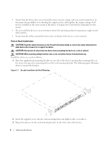
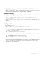
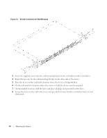
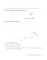
Starting and Configuring the Device After completing all external connections, proceed as follows: • If the device is to be used as an unmanaged switch, there is no need for a terminal connection. • A terminal connection is useful if the device is to be used in a managed mode. NOTE: Before proceeding, read the release notes for this product. The release notes can be downloaded from http://support.dell.com. NOTE: It is recommended that you obtain the most recent revision of the user documentation from the Dell support website at http://support.dell.com. Management Modes The PowerConnect 2808/16/24/48 has a Mode push button on the front panel. The Mode button changes between Managed and Unmanaged modes, or changes from Secure to Managed modes. Connecting the Device to the Network To connect to an uplink port, use Category 6 Shielded Twisted-Pair (STP) cables with RJ-45 connectors at both ends. The RJ-45 ports on the Ethernet device support automatic MediaDependent Interface/Media-Dependent Interface with internal crossover wiring (MDI/MDIX). Standard straight-through twisted-pair cables can be used to connect to any other Ethernet network (systems, servers, switches or routers). NOTICE: Do not plug a phone jack connector into an RJ-45 port. This will damage the Ethernet device. Use only twisted-pair cables with RJ-45 connectors that conform with FCC standards. To connect the device to the network: 1 Attach one end of a Twisted-Pair cable to the device's RJ-45 connector and the other end to a switch or server. 2 Make sure each twisted pair cable does not exceed 328 feet (100 meters) in length. As each connection is made, the link LED corresponding to each port on the device is illuminated (green or amber) indicating that the connection is valid. Starting and Configuring the Device 13
-
 1
1 -
2
-
3
-
4
-
5
-
6
-
7
-
8
-
9
-
 10
10 -
 11
11 -
 12
12 -
 13
13 -
 14
14 -
 15
15 -
 16
16 -
 17
17 -
 18
18 -
 19
19 -
 20
20 -
21
-
22
-
23
-
24
-
25
-
26
-
27
-
28
-
29
-
30
-
31
-
32
-
33
-
34
-
35
-
36
-
37
-
38
-
39
-
40
-
41
-
42
-
43
-
44
-
45
-
46
-
47
-
48
-
49
-
50
-
51
-
52
-
53
-
54
-
55
-
56
-
57
-
58
-
59
-
60
-
61
-
62
-
63
-
64
-
65
-
66
-
67
-
68
-
69
-
70
-
71
-
72
-
73
-
74
-
75
-
76
-
77
-
78
-
79
-
80
-
81
-
82
-
83
-
84
-
85
-
86
-
87
-
88
-
89
-
90
-
91
-
92
-
93
-
94
-
95
-
96
-
97
-
98
-
99
-
100
-
101
-
102
-
103
-
104
-
105
-
106
-
107
-
108
-
109
-
110
-
111
-
112
-
113
-
114
-
115
-
116
-
117
-
118
-
119
-
120
-
121
-
122
-
123
-
124
-
125
-
126
-
127
-
128
-
129
-
130
-
131
-
132
-
133
-
134
-
135
-
136
-
137
-
138
-
139
-
140
-
141
-
142
-
143
-
144
-
145
-
146
-
147
-
148
-
149
-
150
-
151
-
152
-
153
-
154
-
155
-
156
-
157
-
158
-
159
-
160
-
161
-
162
-
163
-
164
-
165
-
166
-
167
-
168
-
169
-
170
-
171
-
172
-
173
-
174
-
175
-
176
-
177
-
178
-
179
-
180
-
181
-
182
-
183
-
184
-
185
-
186
-
187
-
188
-
189
-
190
-
191
-
192
-
193
-
194
-
195
-
196
-
197
-
198
-
199
-
200
-
201
-
202
-
203
-
204
-
205
-
206
-
207
-
208
-
209
-
210
-
211
-
212
-
213
-
214
-
215
-
216
-
217
-
218
-
219
-
220
-
221
-
222
-
223
-
224
-
225
-
226
-
227
-
228
-
229
-
230
-
231
-
232
-
233
-
234
-
235
-
236
-
237
-
238
-
239
-
240
-
241
-
242
-
243
-
244
-
245
-
246
-
247
-
248
-
249
-
250
-
251
-
252
-
253
-
254
-
255
-
256
-
257
-
258
-
259
-
260
 |
 |
