Dell PowerEdge 4600 Rack-to-Tower Conversion Guide - Page 15
Installing the Cover, Metal Feet, and Bezel - power supply replacement
 |
View all Dell PowerEdge 4600 manuals
Add to My Manuals
Save this manual to your list of manuals |
Page 15 highlights
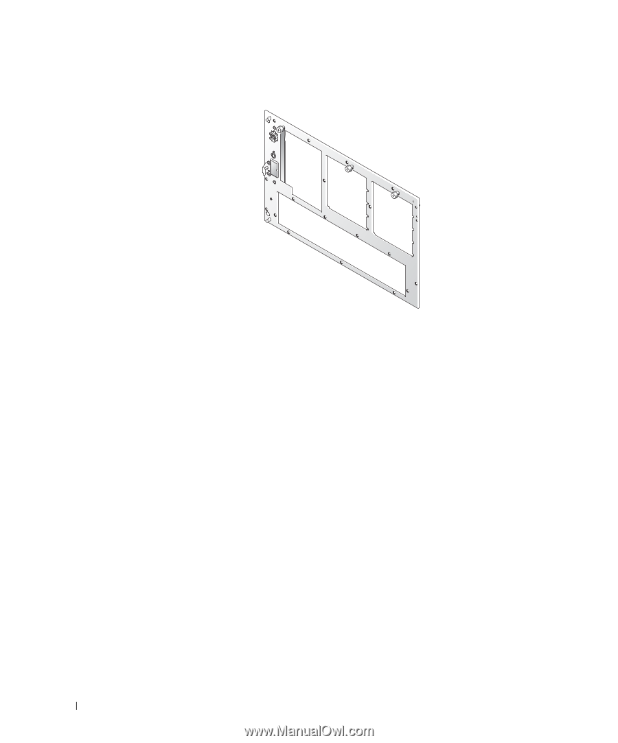
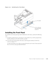
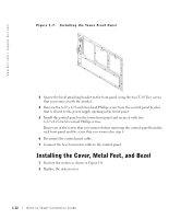
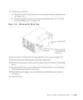
www.dell.com | support.dell.com Figure 1-7. Installing the Tower Front Panel 3 Secure the bezel attaching bracket to the front panel using the four T-10 Torx screws that you removed with the bracket. 4 Remove the 6-32 x 0.25-inch hex-head Phillips screw from the control panel bracket that is closest to the power supply opening in the front panel. 5 Install the control panel on the tower front panel and secure it with two 6-32 x 0.25-inch hex-head Phillips screws. Reuse one of the screws that you removed when removing the control panel from the rack front panel and the screw that you removed in step 4. 6 Reconnect the control panel cable. 7 Connect the bezel connector cable to the control panel. Installing the Cover, Metal Feet, and Bezel 1 Position the system as shown in Figure 1-8. 2 Replace the system cover. 1-12 Rack-to-Tower Conversion Guide
-
 1
1 -
2
-
3
-
4
-
5
-
6
-
7
-
8
-
9
-
 10
10 -
 11
11 -
 12
12 -
 13
13 -
 14
14 -
 15
15 -
 16
16 -
 17
17 -
 18
18 -
 19
19
 |
 |