Dell PowerEdge 6600 Rack Installation Guide (.pdf) - Page 15
Installing the Front Panel
 |
View all Dell PowerEdge 6600 manuals
Add to My Manuals
Save this manual to your list of manuals |
Page 15 highlights
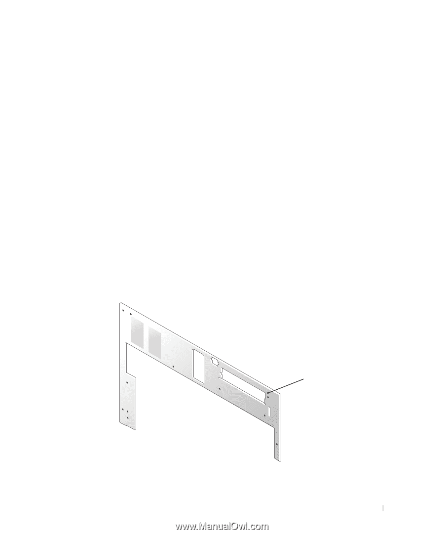
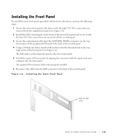
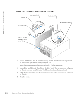
Installing the Front Panel To install the tower front panel (provided with the kit) to the chassis, perform the following steps: 1 Secure the tower front panel to the chassis with the eight T-15 Torx screws that you removed from the original front panel (see Figure 1-6). 2 Install the LCD control panel on the front of the tower front panel and secure it with the four T-15 Torx screws that you removed with the control panel. 3 Secure the control panel cable from the CONTROL PANEL connector (on the top front corner of the peripheral I/O board) to the back of the control panel. 4 Using a 1/4-inch nut driver, install a ball stud nut onto the threaded stud in the top right corner of the front panel (see Figure 1-6). The ball stud is used to latch the bezel to the tower front panel. 5 Install the square LED connector by aligning the connector with the square hole and seating it into the front panel. The square LED connector clicks when properly installed. 6 Reconnect the cable from the LED connector to the back of the control panel. Figure 1-6. Installing the Tower Front Panel hole for ball stud Rack-to-Tower Conversion Guide 1-11
-
 1
1 -
2
-
3
-
4
-
5
-
6
-
7
-
8
-
9
-
 10
10 -
 11
11 -
 12
12 -
 13
13 -
 14
14 -
 15
15 -
 16
16 -
 17
17 -
 18
18 -
 19
19 -
 20
20 -
21
-
22
 |
 |