Dell PowerEdge 7150 Rack Installation Guide - Page 17
Installing a System in the Rack, Installing the System
 |
View all Dell PowerEdge 7150 manuals
Add to My Manuals
Save this manual to your list of manuals |
Page 17 highlights
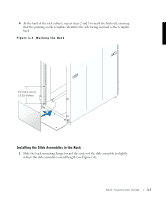
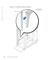
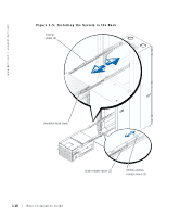
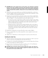
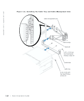
2 The mounting flange on each end of the slide assembly has two hooks that fit through holes in the vertical rail. Position the slide assembly mounting flange against the inner side of the rack's front vertical rail so that the uppermost hook is in the topmost hole and just below the top of the system position you marked on the rack. 3 Press the front mounting flange against the inside surface of the front rail, and press down. The mounting hooks move down, and the square latching tab pops into the square hole just below the upper mounting hook. 4 Slide the back mounting flange backward to increase the slide assembly's length until the back mounting flange fits snugly against the inner side of the back vertical rail. 5 Press the back mounting flange against the inside surface of the back rail, and press down. The mounting hooks move down, and the square tab pops into the square hole just below the upper mounting hook. 6 Repeat steps 1 through 5 to install the second slide assembly. Installing a System in the Rack The subsections that follow provide instructions for installing a system in the rack. Installing the System CAUTION: If you are installing more than one system, install the first system in the lowest available position in the rack. Complete the installation of the first system in the rack before starting the second. Never pull more than one system out of the rack at a time. WARNING: Installing multiple systems in a rack will require up to four people and may require a sturdy, elevated platform to stand on. A mechanical lifting platform or similar equipment of the proper capacity may also be useful. If you attempt to lift the system without enough people to safely perform the task, you risk personal injury to yourself and to others and damage to the system. 1 Pull the two interior slides out of the rack until they lock in the fully extended position (see Figure 1-5). Rack Installation Guide 1-9
-
 1
1 -
2
-
3
-
4
-
5
-
6
-
7
-
8
-
9
-
10
-
11
-
 12
12 -
 13
13 -
 14
14 -
 15
15 -
 16
16 -
 17
17 -
 18
18 -
 19
19 -
 20
20 -
 21
21 -
 22
22 -
23
-
24
 |
 |