Dell PowerEdge 7150 Rack Installation Guide - Page 19
Installing the Cable Tray
 |
View all Dell PowerEdge 7150 manuals
Add to My Manuals
Save this manual to your list of manuals |
Page 19 highlights
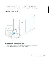
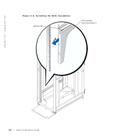
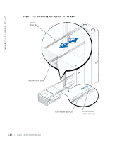
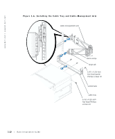
CAUTION: Due to the weight and size of the system, never attempt to install the system in the slide assemblies by yourself. Even with some internal components removed, the system may require four people to lift it into position and install it on the extended slide assemblies. Always use the chassis handles when lifting the system. 2 To make the system easier to lift, remove and label the hard-disk drives, and remove the power supplies and fans. For instructions on removing system components, see the system's Installation and Troubleshooting Guide. 3 Using two to four people, lift the system into position in front of the extended slides. The shoulder studs on the side of the chassis must enter the inner slots of the interior slides (see Figure 1-5). You can install the system on the slides two ways: • From the front of the extended slide assemblies, align the shoulder studs with the inner slots in the interior slides and push the system into the slide assemblies until all three shoulder studs have entered the interior slides and the yellow chassis release lever locks the system in place. • Position the system so that the center and back shoulder studs on each side are directly above the openings in the interior slides. Lower the system into the rack and push the system into the slide assemblies until the front shoulder screw on each side enters the interior slides and the yellow chassis release lever locks the system in place. 4 Reinstall any components you removed from the system to make it lighter. 5 Press in on the flat slide release latch and push the system completely into the rack (see Figure 1-5). 6 Tighten the two thumbscrews on the front panel to secure the system to the rack. Installing the Cable Tray 1 Attach the cable tray to the back of the system by inserting the two slots on each end of the tray onto the corresponding tabs in the back of the chassis. 2 Use three 6-32 x 0.25-inch hex-head taptite screws to secure the bottom lip of the tray to holes just beneath the expansion card area. 3 Secure the side of the chassis to the cable tray with two 6-32 x 0.25-inch flat-head Phillips screws on each side of the chassis (see Figure 1-6). CAUTION: Do not grasp the cable tray when lifting the system. The cable tray and its mounting are not sturdy enough to support the weight of the system. Lift the system by the chassis handles only. Rack Installation Guide 1-11
-
 1
1 -
2
-
3
-
4
-
5
-
6
-
7
-
8
-
9
-
10
-
11
-
12
-
13
-
 14
14 -
 15
15 -
 16
16 -
 17
17 -
 18
18 -
 19
19 -
 20
20 -
 21
21 -
 22
22 -
 23
23 -
 24
24
 |
 |